by Elaina Adams | December 1, 2012 2:01 pm
By John Burrows, P.Eng., and Jim Gallagher
The efficiency of new buildings designed to meet the 2011 National Energy Code of Canada for Buildings (NECB) will be significantly better than that of most older structures. It replaces the 1997 Model National Energy Code for Buildings (MNECB), and will become a requirement in the adopting provinces and territories. Consequently, it is critical architects, specifiers, engineers, owners, and other members of a project team understand its requirements. (This article is based on material published by the National Research Council of Canada (NRC). For more detailed information about NECB, design/construction professionals can refer to the free, online presentations available at NRC’s National Codes website. Visit www.nationalcodes.nrc.gc.ca/eng/presentations/2011_necb_presentations.shtml[2]. To order a copy of the 2011 code, visit www.nrc.gc.ca/virtualstore[3]).
The code applies to new buildings and additions, yielding an average of 26 per cent overall energy performance improvement compared to MNECB. It provides designers more flexibility by offering several compliance paths. It addresses the energy used by the building, irrespective of the energy source, with no exemption for any type of assembly construction or occupancy.
However, its scope does not include housing and small buildings covered by Part 9 of the National Building Code of Canada (NBC). Instead, a new section of NBC Part 9 will introduce updated energy requirements for these buildings. NECB also does not apply to farm buildings.
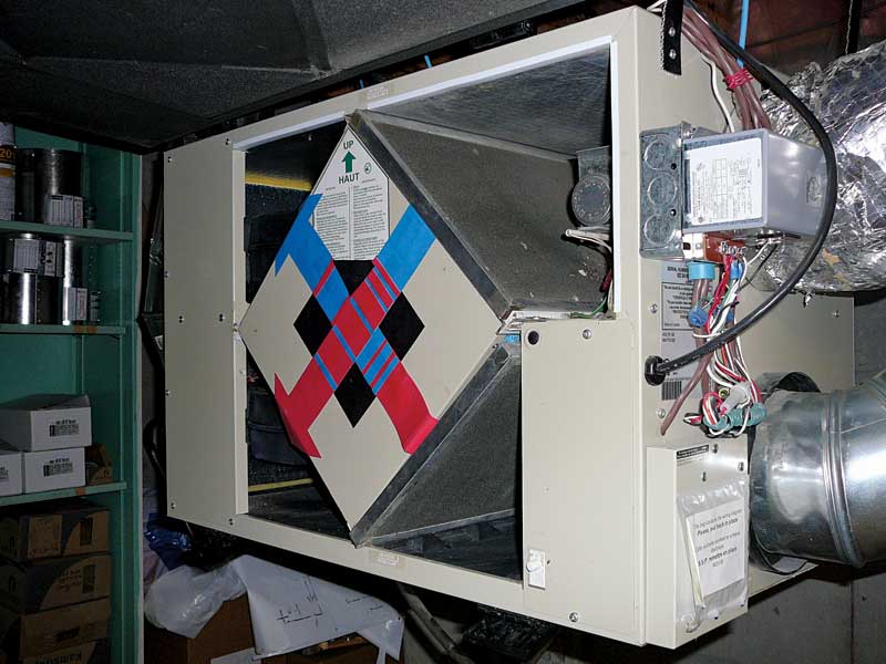
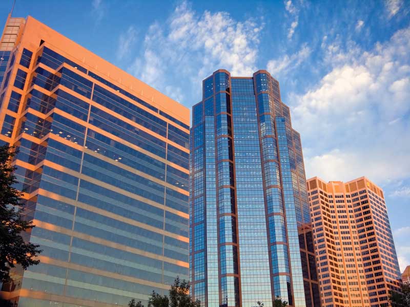
The code’s development was initiated by the Canadian Commission on Building and Fire Codes (CCBFC) in response to stakeholder requests to add a new objective on energy efficiency to the National Model Construction Codes. It is the result of an extensive consultation process involving representatives from Canadian industry, multiple levels of government (i.e. federal, provincial, territorial, and municipal), the construction industry, and the general public. Both the National Research Council-Institute (through its construction research arm, NRC Construction) and Natural Resources Canada (NRCan) provided technical support. The latter supplied funding as part of its commitment to improve the built environment’s energy efficiency and reduce greenhouse gas (GHG) emissions.
This article provides detailed information on the energy requirements for NECB, Part 3 (“Building Envelope”), and also outlines:
The code offers three compliance paths:
Part 3, building envelope
Part 3 of NECB deals with the building envelope, with various thermal/moisture protection components discussed in the paragraphs
that follow.
Prescriptive path: insulation
There are provisions for protecting insulation against degradation of thermal properties due to:
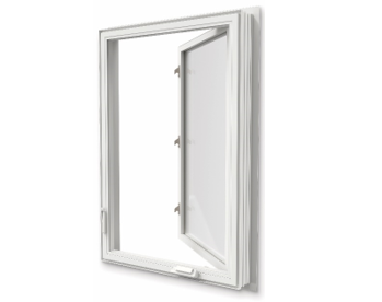
There are also requirements for the continuity of insulation so prescribed levels are provided over the entire building envelope. Maximum overall thermal transmittances (i.e. U-values) are given for above-ground opaque building assemblies, fenestration, doors and access hatches, and assemblies in contact with the ground. The code’s insulation level demands are based on the heating degree-days for given locations, as found in NBC’s Appendix C.
The climatic zones in NECB have been set using 1000 heating degree-day gradations. The zone names are the same as those used in American Society of Heating, Refrigerating, and Air-conditioning Engineers (ASHRAE) 90.1, Energy Standard for Buildings Except Low-rise Residential Buildings, except Zone 7 is split into two 1000 degree-day zones called 7A and 7B to better reflect the reality of the Canadian climate.
Prescriptive path: above-ground assemblies
The prescriptive requirements set a maximum overall U-value for the building enclosure’s above-ground walls, roofs, and floors that vary according to the heating degree-day location of the building.
Zone 4 is for areas with less than 3000 heating degree-days—examples include Victoria and the B.C. Lower Mainland. For these locales, the maximum overall U-value for walls is 0.315, which is equivalent to a minimum effective RSI of 3.17 or approximately R-18.
Zone 8 includes areas with 7000 heating degree-days or more, such as most of the Yukon, Northwest Territories, and Nunavut. Here, the maximum overall U-value for walls is 0.183, which translates to a minimum effective RSI of 5.46 or R-31. Roofs and floors in Zone 8 have a maximum overall U-value of 0.142—a minimum effective RSI of 7.04 or R-40.
All the maximum allowable U-values are reduced by 20 per cent (i.e. more stringent) for various assemblies containing embedded radiant heating and/or cooling cables, pipes, or membranes.
For windows, the requirements for Zone 4 can typically be achieved using the equivalent of a good-quality, thermally broken aluminum frame, double-glazing units with low-emissivity (low-e) coating and a non-metallic spacer.
The requirements of Zones 5, 6, 7A, and 7B can typically be met using the equivalent of a good-quality, thermally broken aluminum frame, low-e double-glazing units, a non-metallic spacer, and argon fill. Zone 8, on the other hand, typically needs the equivalent of a good-quality, thermally broken aluminum frame, triple-glazing units with low-e, non-metallic spacers, and argon fill.
Prescriptive path: assemblies in contact with ground
The maximum U-values for building envelope assemblies in contact with the ground vary according to the building project’s heating degree-day location. Roofs that are less than 1.2 m (4 ft) below ground—for example, the roof of an underground parking garage extending beyond the building footprint—must comply with the required U-values.
Walls must be insulated to required levels for a distance of 2.4 m (8 ft) below ground or to the bottom of the wall, whichever occurs first. Where footings are less than 0.6 m (2 ft) below ground, the insulation level demanded by the table must be placed on the top or bottom of the floor slab for 1.2 m.
The U-values for walls with embedded radiant heating cables, heating or cooling pipes, or membranes are reduced by 20 per cent (i.e. more stringent) from prescribed U-values.
Floors that are less than 0.6 m below grade are required to be insulated. Floors that contain embedded heating ductwork, cables, or heating or cooling pipes must be insulated over their full area. Otherwise, the floors have to be insulated for 1.2 m around their entire perimeter.
Prescriptive path: fenestration
The maximum prescriptive skylight area limit is five per cent of the gross roof area. The maximum allowable vertical fenestration and door area to gross wall area ratio (FDWR) is determined based on the heating degree-days for the building location.
For heating degree-day values of 4000 or less (e.g. Toronto, Vancouver, and Victoria), the FDWR limit is set at 40 per cent. At heating degree-day values of 7000 or higher (e.g. Yellowknife and Iqaluit), the FDWR limit is set at 20 per cent.
For sites with heating degree-days between 4000 and 7000, FDWR varies linearly and the limit can either be calculated using an equation in NEBC or interpolated using a table of values in the code’s appendix.
Prescriptive path: air leakage
All opaque building assemblies are required to have an air barrier assembly. Metal and glass curtain walls and fixed and operable windows must meet air leakage test levels under fixed pressures in accordance with the standards cited in NECB.
Under the code, doors have to meet air leakage test requirements. A higher air leakage rate is allowed for revolving, automatic sliding, and main entry exterior doors. All loading docks that interface with truck boxes must have weather seals.
Trade-off paths and Part 3
There are two trade-off paths for Part 3 of the energy code—simple and detailed. The former allows for the trading of U-values and areas of fenestration/doors based on a simple calculation. To keep this option very simple, the following limitations are placed on its use:
The detailed trade-off path is a scaled-down version of the whole-building performance compliance path discussed later in this article (i.e. NECB Part 8). It requires the energy use attributed to the proposed building envelope be less than that of its counterpart in a reference building or one that would result if constructed using the prescriptive path.
For both the simple and detailed methods, the reference building must employ the prescriptive path’s U-values and fenestration-and-door-to-wall ratio limits. The parameters to include in the detailed trade-off calculations are:
Lighting under the code
NECB Part 4 covers lighting components and systems connected to a building’s electrical service. Certain lighting applications are exempted, such as emergency lighting that is automatically off during normal building operation, and any lighting in dwelling units. Another exclusion occurs where the authority having jurisdiction (AHJ) accepts the fact the occupancy’s nature makes it impractical to apply all of the requirements.
Prescriptive path
For dusk-to-dawn operation, exterior lighting must be controlled by an astronomical time control or a photosensor. For other applications, lighting must be controlled by:
Lighting for exterior entrances is exempted.
For interior lighting, the basic principle of the prescriptive requirements is the actual installed power cannot exceed the allowance in the code as calculated using either the building area method or the space-by-space method. It is important to note only one of these methods can be used for the entire building. The space-by-space method can always be employed, but some criteria govern the use of the building area method.
To determine the interior lighting power allowance using the space-by-space method, the lighting power density for each space use (or its equivalent) is determined from a values table. This is then multiplied by the space’s gross interior floor area. The process is done for each space, and all are summed to yield the interior power lighting allowance for the entire project. The result is then compared against the installed interior lighting power.
As lighting of unoccupied interior spaces is an unnecessary use of energy, NECB calls for automatic lighting controls for many applications. Automatic controls are needed to shut interior lighting off in all spaces using either time-of-day operation, occupant sensors, or signals from a control or alarm system that the area
is unoccupied.
Areas exempted from the interior lighting control requirements include those where:
Each enclosed space must have at least one control device to independently turn off the general lighting within it. Certain spaces require the control be an occupant sensor, while others require a control device that can be activated either manually by an occupant or automatically by a sensor.
There are requirements for automatic daylighting controls for toplighting (i.e. skylights and rooftop monitors). When the daylighted area under skylights and rooftop monitors is greater than 400 m2 (about 4300 sf), a photocontrol must be installed to reduce general lighting.
Trade-off path
The trade-off method can only be used for interior lighting. The basic equation for the lighting trade-off path is the installed interior lighting energy (IILE) must be less than or equal to the interior lighting energy allowance (ILEA). The ILEA is calculated in accordance with the prescriptive space-by-space method.
The trade-off path uses a more detailed calculation procedure for allowable and installed lighting than the prescriptive path requires. It uses a series of equations and factors to calculate IILE and ILEA.
HVAC and NECB
Part 5 of the energy code deals with HVAC systems.
Prescriptive path
The minimum energy performance efficiencies of HVAC equipment (i.e. boilers, furnaces, air-conditioners, heat pumps, and water chillers) are stipulated in NECB. The system’s fuel source and capacity are considered in the performance required, and the equipment must not be under- or over-sized.
Air distribution systems must have a means to permit balancing. Ducts must be sealed and tested for air leakage. Duct and plenum insulation requirements depend on the difference between the temperature in the space where a duct is located and the temperature of the air carried in the duct. If a duct is used to carry both heated and cooled air, the largest temperature difference is employed to determine the insulation needed.
HVAC systems with mechanical cooling capacities larger than 20 kW, and air-handlers greater than 1500 L/s (about 3180 cfm), must be equipped with a means to cool with outdoor air. HVAC systems in dwelling units and hotel and motel rooms are exempted from this requirement. In general, outdoor air intakes and ducts or openings discharging air to the outdoors must have motorized dampers.
When an air economizer is used to meet the requirement for cooling with outdoor air, it must be capable of mixing 100 per cent outside air with the return air. If a water economizer is selected to achieve this goal, it must be capable of providing 100 per cent of the cooling load based on outdoor air temperature.
In cases when the flow from a central exhaust in multi-unit residential buildings is greater than 150 kW, heat recovery is required, but there is an exemption for climatic Zones 4, 5, and 6. Heat recovery applies only to the principal exhaust, not the exhausts for kitchen hoods or bathrooms. A heat-recovery apparatus used for a dwelling unit must be able to recover 50 per cent of the sensible heat. Although humidity is not included in the heat content calculation, an energy-recovery ventilator is permitted to be used to meet NECB’s heat-recovery demands.
The energy code mandates 40 per cent sensible heat recovery from the exhaust air of spaces containing pools with a surface area greater than 10 m2 (108 sf). An exemption is permitted where a dehumidification system provides 80 per cent of the dehumidification that would be accomplished by an exhaust system.
Under the code, ice arenas and curling rinks with a heating load elsewhere in the building must recover heat from the refrigeration system. The code provisions allow use of this recovered heat for space heating or service water heating.
Hydronic systems need to be able to be balanced. There are also piping insulation requirements based on the operating temperature of fluid, insulating material conductivity, and pipe diameter. In general, variable-flow pumping systems with a total pump system power (or nameplate power) greater than 7.5 kW must be able to reduce flow by 50 per cent or less.
Temperature control is required at various points in an HVAC system in addition to the control space comfort. Independent perimeter systems must have one control per building orientation of 15 m (50 ft) or longer.
Systems serving dwelling units and areas not intended to operate continuously, and that have a heating or cooling capacity requirement greater than 5 kW, must have set-back or shut-down controls for periods of non-use. Seasonal shut-down controls are also mandatory on pumping systems.
Air distribution controls are required to allow the stoppage or reduction of airflow. Each air distribution system serving multiple temperature-control zones must have airflow control areas no greater than 2500 m2 (26,910 sf).
Controls are necessary on ice- and snow-melt heaters to allow them to be shut down when not required. A completely new NECB provision addresses vestibule overheating by calling for the installation of a control device capable of limiting the maximum temperature in vestibules to 15 C (60 F).
Trade-off path
Since the trade-off path considers the HVAC assembly as a whole, improvement in one part of the system is allowed to compensate for another component that does not meet the prescriptive requirement. The total efficiency of the proposed system needs to be greater than or equal to the total efficiency of the reference system—in other words, it must consume less energy. The reference system models the prescriptive requirements.
The trade-off path contains certain limitations:
Service water heating
NECB Part 6 covers heating equipment, controls, piping, and pumping that form part of a service water heating (SWH) system.
Prescriptive path
Installations using SWH equipment for both space and service water heating must meet the performance requirements of both Parts 5 and 6. Installations employing space water-heating to indirectly heat service water must use equipment meeting whatever is greater—the performance efficiency of the space or SWH equipment.
In general, piping insulation requirements are based on the fluid temperature involved.
Controls addressed in Part 6 include those for:
Automatic temperature controls that allow adjustment between the lowest and highest acceptable temperature settings for the intended use are required for all systems with storage tanks. Flows are limited to 9.5 L (2.5 gal) per minute for showers and 8.3 L (2.2 gal) for lavatories. Automatic shut-off valves are called for in assembly occupancy spaces.
A cover is required for heated outdoor swimming pools and tubs. It must be large enough to cover 90 per cent of the water surface area. Shut-off controls are mandated to shut down pool pumps and heaters during periods of non-use.
Trade-off path
The trade-off path considers the SWH system as a whole, allowing improvement in other system parts to compensate for one component not meeting a prescriptive requirement. This approach means the SWH system boundaries must be clearly identified to properly define the components making up a system. Boundaries were established for each system type, and the components are provided in a table.
NECB and electrical power
Part 7 of NECB applies to the electrical power systems and motors connected to the building’s electrical service. There is no trade-off path.
Electrical distribution systems with a load-carrying capacity greater than 250 kilovolt-amps must have a means to monitor the energy consumption of HVAC systems, and both interior and exterior lighting. Electrical distribution systems for buildings with dwelling units must have a means to separately monitor the total building, as well as each individual tenant or dwelling unit, excluding shared systems.
There are prescriptive requirements for voltage drop. Feeder conductors must be sized for a maximum voltage drop of two per cent at design load. Branch circuit conductors must be sized for a maximum voltage drop of three per cent.
Transformers and motors must meet the minimum efficiency of referenced standards.
Building energy performance compliance path
Part 8 provides an alternative to the prescriptive requirements and trade-off of other parts of NECB. Compliance is demonstrated by showing a building will not use more energy than it would if it were to comply with the prescriptive path. Several software programs that have been evaluated against ASHRAE 140, Standard Method of Test for the Evaluation of Building Energy Analysis Computer Programs, or a similar software test method can be used to design using the performance compliance path.
Conclusion
In general, the 2011 National Energy Code of Canada for Buildings provides a 26 per cent overall energy performance improvement compared with MNECB. This improvement is a weighted average for the whole country and is based on many factors, including the energy performance level from which a region started.
NECB is an advance that will yield significant energy savings and place Canada on a comparable footing with countries that lead the world in energy-efficient building construction.
John Burrows, P.Eng., is an Ottawa-based consultant and technical writer. With an engineering background, he has been writing for NRC Construction (formerly the National Research Council Institute for Research in Construction [NRC-IRC]) for the past 11 years.
Jim Gallagher is the former manager (retired) of publication services at NRC Construction. He can be contacted at jim.gallagher@nrc.ca[9].
Source URL: https://www.constructioncanada.net/staying-current-with-canadas-energy-code/
Copyright ©2023 Construction Canada unless otherwise noted.