Dynamic fan testing: Validating facade performance under simulated wind-driven rain
As performance demands on building enclosures must meet high standards for durability, weather, and energy performance, facade systems are becoming more complex. These systems remain vulnerable to water infiltration without proper detailing, fabrication, and installation. Poor water management can lead to significant issues, including material deterioration, corrosion, organic growth, and damage to interior finishes. These failures often result in costly repairs, construction delays, and potential litigation. Design alone does not guarantee reliable long-term performance in the field. Variability in design, fabrication, installation, cross-trade coordination, and site conditions can affect system performance. As a result, field testing is critical to verification, providing objective data to confirm assemblies meet performance expectations.
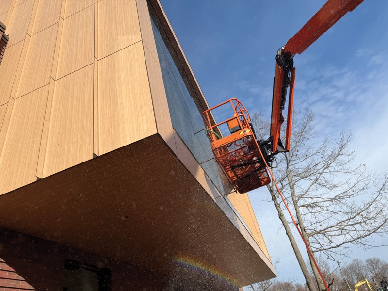
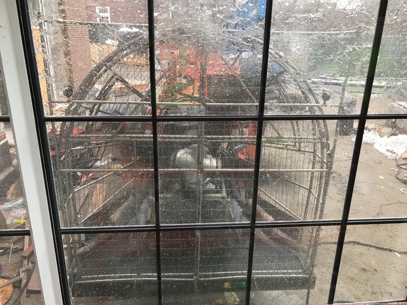
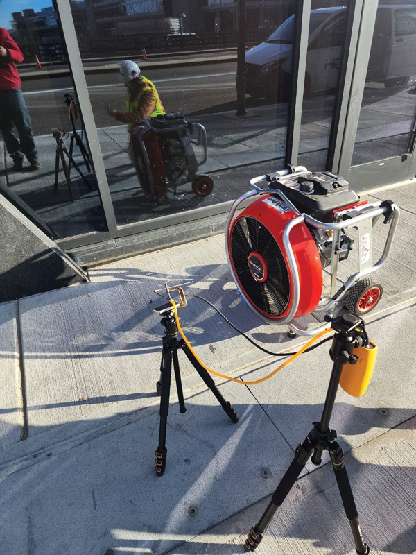
Dynamic fan testing is one of several methods used to evaluate water penetration resistance. The primary standard used for this testing is AAMA 501.1-17, Standard Test Method for Water Penetration of Windows, Curtain Walls, and Doors Using Dynamic Pressure. This standard establishes procedures for evaluating the water penetration resistance of exterior fenestration systems, including curtain walls, storefronts, windows, and doors. The test attempts to simulate wind-driven rain by directing airflow from a high-speed fan toward the facade while water is uniformly applied through a spray rack system. The combination of airflow and water application creates pressure conditions that more closely replicate actual weather exposure than static testing methods. This testing has traditionally been used primarily for large-scale performance mockups due to the size of the required equipment (e.g. large airplane engines). With the development of smaller fans, this testing is becoming increasingly common at construction sites (see Photo 1), though AAMA 501.1-17 is a laboratory-based standard. The Fenestration and Glazing Industry Alliance (FGIA) is developing a field-based standard that is likely to be published in late 2026. A few of the forthcoming updates are summarized at the end of this article.
Although AAMA 501.1 is commonly referred to as a “dynamic” pressure test, the test itself does not create fluctuating or cyclic pressure conditions. Instead, the fan produces a steady airflow toward the facade, resulting in relatively constant pressure across the test area. The term “dynamic pressure” refers to the pressure generated by moving air rather than the static air pressure differential created within a sealed chamber. When properly executed, dynamic fan testing serves as a valuable tool within broader enclosure testing, aiding other methods and confirming overall system performance. This article aims to provide a better understanding of the general testing procedure and its benefits.
Applications and advantages
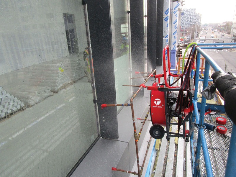
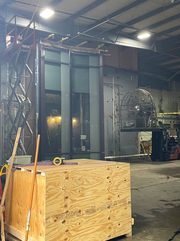
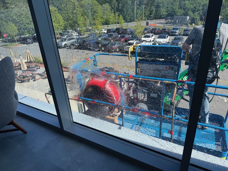
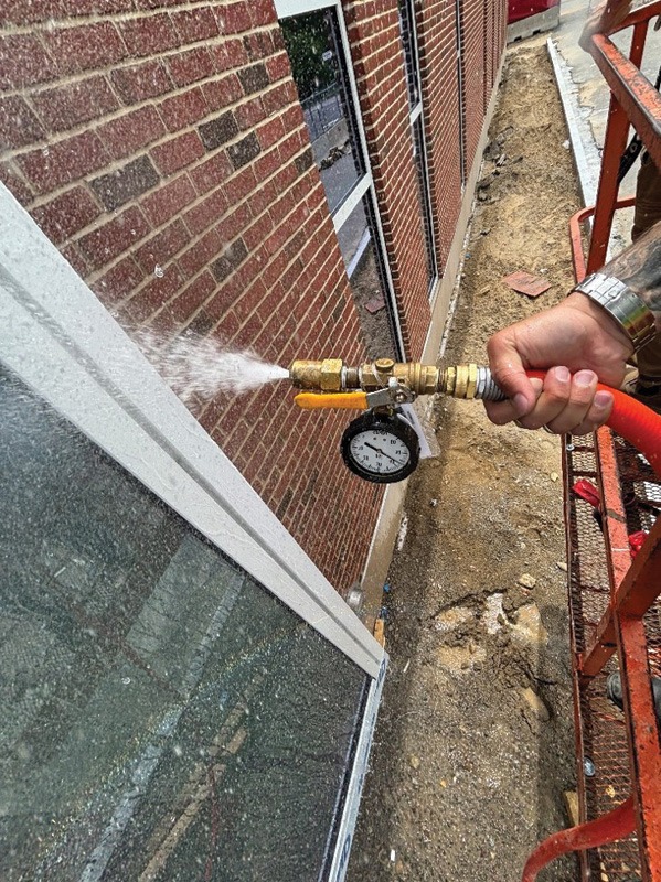
AAMA 501.1 testing may be conducted on laboratory or field mockups before construction (see Photo 2), and on installed assemblies to confirm installation quality and identify deficiencies before project completion (see Photo 3).
It is also frequently used during investigations of existing buildings to help identify leakage pathways and evaluate facade performance under simulated wind-driven rain conditions. This can be particularly useful when leaks are difficult to reproduce using conventional hose testing methods.
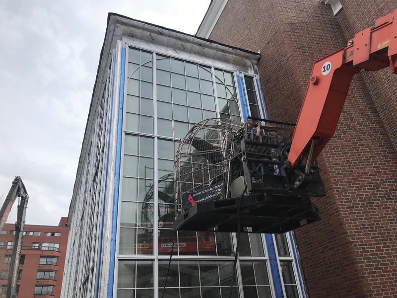
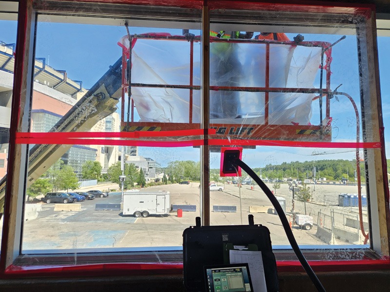
Dynamic fan testing is most applied to buildings with unitized curtain walls (see Photo 4 on page 10), where interior chamber construction is impractical and time-consuming. The test is also valuable for simpler facades, as it can quickly assess a wide area.
In some cases, AAMA 501.1 testing may also be used as an alternative to ASTM E1105, Standard Test Method for Field Determination of Water Penetration of Installed Exterior Windows, Skylights, Doors, and Curtain Walls, by Uniform or Cyclic Static Air Pressure Difference, when chamber installation is impractical, disruptive, or cost-prohibitive. Unlike chamber testing, which requires sealing the perimeter of the test area and establishing a static pressure differential within the assembly, AAMA 501.1 uses airflow generated by a high-speed fan to create dynamic pressure conditions at the exterior. Therefore, the method is often more efficient in the field, with less disruption to interior spaces and building occupants. AAMA 501.1 is not intended to replace ASTM E1105 in all situations, but it can be a practical and effective alternative in some cases. It is crucial to discuss the application of this testing with all stakeholders, such as the installer and manufacturer, as some products may not be certified under AAMA 501.1.
Testing basics, setup, and calibration methods
Proper setup and calibration are critical to obtaining valid, reproducible results. While recalibration is not required for every test, it is ultimately up to the testing agency to determine. Currently, recalibration is required at least every six months. The following step-by-step procedures combine the author’s methods with AAMA 501.1-17 guidelines.
Fan and equipment inspection
- Fan blade clearance—Visually inspect that fan blades are not touching the guard. Clearance must be uniform around the entire perimeter. Any contact indicates improper installation or damage requiring correction before operation.
- Mounting security—Verify all securing straps, bolts, and fasteners are tight. Secure any excess strap material away from rotating components.
- Work area clearance—Ensure no unnecessary objects or individuals are positioned in front of the fan. Do not activate the fan in environments around loose debris, such as leaves, dust, paper, or construction materials, as high-velocity airflow will propel them.
Placement and securement
- Inspect the elevated work platform thoroughly before lifting the fan. Remove all debris, loose materials, and potential hazards.
- Position the platform or mounting structure on the elevated work platform on a level surface to securely support the fan.
- Lift the fan onto the elevated work platform using appropriate equipment and trained personnel (see Photo 5).
- Secure the fan to the elevated work platform structure using all provided attachment points, straps, and fasteners. All securing hardware must be tight and verified secure.
- Verify that the base of the elevated work platform is in firm contact with the ground. Ground contact stabilizes the entire assembly and is essential for accurate velocity measurements during calibration.
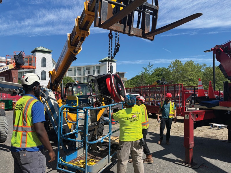
There are many ways to mount a high-speed fan, depending on its size and the project site’s requirements. A large turbo-prop-style fan, commonly used by dedicated testing companies, would typically be mounted to telehandler-style mobile forklifts (see Photo 6 on page 11). Smaller purpose-built fans can be placed within aerial lifts.
Velocity measurement setup
Velocity calibration is arguably the most critical step in AAMA 501.1-17 testing. Velocity must be measured at four quadrants of the fan discharge face to verify uniform airflow across the test area. All velocity measurements are performed using a Pitot tube connected to a pressure-measuring instrument that converts pressure readings to velocity in meters per second (m/s).
Pitot tube setup and quadrant measurement
- Assemble the tripod or measurement frame at the test location, positioned to measure velocity at the four quadrants of the fan discharge face as specified by AAMA 501.1-17.
- Configure the measurement instrument to display velocity in meters per second (m/s).
- Connect the Pitot tube to the measurement instrument using the connecting tubes provided. Ensure all connections are secure to prevent air leakage.
- Zero the measurement instrument before beginning calibration to account for atmospheric pressure variations at the test site.
- Secure the Pitot tube firmly to the measurement frame, ensuring it will not shift during
the measurements. - Position the Pitot tube at the first quadrant measurement point as specified by AAMA 501.1-17.
- Orient the Pitot tube perpendicular to the fan discharge face using angle guides and bubble levels. The tube must point directly at the fan outlet, not at an angle (see Photo 7 on page 12.)
- Pitot tube orientation is a common source of measurement error. Even small angular shifts produce significantly inaccurate velocity readings. Verify alignment at each quadrant measurement point before recording data.
Fan calibration and velocity measurement
Fan calibration is the process of measuring airflow velocity at the four specified quadrant points and confirming that the fan produces the dynamic pressure required by AAMA 501.1-17. This is the single most important step in the entire testing procedure. Without proper calibration, test results are invalid.
Test pressure and equivalent wind velocity
AAMA 501.1-17 specifies standard test pressures and their equivalent wind velocities. Table 1 shows the relationship between pressure and velocity for industry-standard test conditions.
Table 1: Wind velocity vs. Equivalent industry standard test pressure (AAMA 501.1-17, Section 5.2)
| Test Pressure | Equivalent Wind Velocity |
| 300 Pa (6.24 psf) | 22.1 m/s (50 mph) |
| 380 Pa (8.00 psf) | 24.9 m/s (56 mph) |
| 480 Pa (10.00 psf) | 28.0 m/s (63 mph) |
| 580 Pa (12.00 psf) | 30.8 m/s (69 mph) |
| 720 Pa (15.00 psf) | 34.3 m/s (77 mph) |
Select the test pressure appropriate for the project requirements. The fan throttle must be adjusted to achieve the equivalent wind velocity corresponding to the specified test pressure.
Measuring velocity at each quadrant
- Activate the fan and allow it to reach steady-state operation
- Verify that the velocity instrument readings
are stable. Minor variations are normal
(e.g. +/- 1.1 m/s); larger fluctuations indicate turbulent flow or equipment issues. - Record the velocity at each of the four
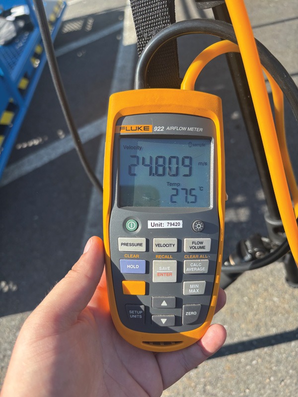
quadrant points. Using video recording, identify the maximum velocity occurring within a one-minute duration for each quadrant (see Photo 8 on page 12). - Turn off the fan between measurements at each quadrant to allow readings to stabilize.
Velocity-to-pressure conversion
Once velocity measurements are recorded in all four quadrants, convert these readings to equivalent velocity pressure and verify that the velocity aligns with the test pressure.
Convert metric to imperial units
Velocity (m/s) × 2.23693 = Velocity (mph)
Calculate equivalent velocity pressure
Using the formula specified by AAMA 501.1-17:
P = 0.00256 × V²
P = velocity pressure in pounds per square foot (psf)
V = velocity in mph
Calculate the mean velocity and standard deviation of velocity readings from all four quadrant points. Verify that all measurements fall within the tolerance of +\- 1.1 m/s (+\- 2.5 mph) specified by AAMA 501.1-17. If all points are within tolerance, calibration is complete. If any measurement falls outside the tolerance band, the fan speed must be recalibrated before testing.
AAMA 501.1-17 test parameters
Once calibration is complete and confirmed to meet standard requirements, the following test parameters apply per AAMA 501.1-17:
- Test duration—Testing must continue for a minimum of 15 minutes. If the equipment stops at any point during the test (e.g. the fan runs out of fuel), the test must restart and run continuously again for 15 minutes.
- Water application rate—Water must be applied at 3.4 L/m²·min (5 gal/ft²·h) measured at the face of the specimen. This is typically provided by a spray rack, which must also be calibrated in accordance with AAMA 501.1-17.
- Test observation—Continuously observe the specimen for signs of water penetration. Document the location, time of occurrence, and severity of any leakage observed during the 15-minute test period.
- Test area coverage—The effective test area per fan position is determined by the propeller diameter. For larger surfaces, reposition the fan on a square grid with spacing equal to two times the propeller diameter, covering the entire surface to be tested per AAMA 501.1-17.
AAMA 501.1-17 defines unacceptable water penetration as the occurrence of any of the following conditions. If it visibly appears beyond a plane parallel to the glazing (the vertical plane) intersecting the innermost projection of the test specimen, not including interior trim and hardware, per ASTM E331, Standard Test Method for Water Penetration of Exterior Windows, Skylights, Doors, and Curtain Walls by Uniform Static Air Pressure Difference. Additionally, water penetrating through a perimeter detail and not contained within drained flashing, gutters, and sills incorporated in the mockup installation constitutes a failure.
Water accumulation on interior members of the system is allowed up to the specified limits: 15 mL (0.5 oz) maximum for individual locations, and cumulative totals not exceeding 15 mL (0.5 oz) for specimens ≤ 23 m2 (250 sf) (prorated for larger specimens).
If any water leakage is observed that bypasses the building’s intended drainage and containment systems, the assembly should be considered to have failed.
While AAMA 501.1-17 permits minor water accumulation within prescribed limits, water that penetrates beyond the designed drainage paths compromises the assembly’s intended water management strategy. The goal of any water penetration test is zero uncontrolled water leakage.
Forthcoming AAMA 501.1 field-testing standard
Although AAMA 501.1-17 is commonly used in the field, it was originally developed as a laboratory test method and does not fully address the challenges of field testing. The FGIA task groups and committees are currently updating the lab version of AAMA 501.1 and developing a separate field version, with both standards anticipated for publication in late 2026. The new standard is intended to address limitations in the current version of AAMA 501.1-17 as they relate to field testing and to provide more comprehensive guidance for implementing dynamic pressure water penetration testing under real-world field conditions. Here is a summary of the pertinent changes and guidance that will likely be in the forthcoming field-testing standard below.
- Products in/out of scope—The field standard will identify which fenestration systems can or cannot be tested under the field standard. Products certified under the North American Fenestration Standard (NAFS) are unlikely to be included in the new field standard.
- Field preparation—The field standard will provide specific guidance on the installation progress of adjacent materials around the test sample. In general, exterior cladding, rainscreens, and associated components, including the perimeter sealants, should be installed adjacent to the test sample. The standard also guides how to isolate fenestration systems when testing the air and vapor barrier under this standard.
- Wind speed calibration requirements—The field standard will provide additional calibration guidance under field conditions and increases the allowance for variability in the wind speed. The field standard will also allow for a reduction in the maximum wind speed if the desired wind speed cannot be achieved in the field.
- Recalibration frequency—The frequency of recalibration remains unchanged in the field standard (e.g. minimum once every six months). The author’s opinion is that the fan should be recalibrated before each test, as field testing conditions can significantly affect the equipment’s accuracy.
When published, AAMA 501.1 will provide practitioners with more definitive guidance for field dynamic fan testing and will help improve the reliability and defensibility of test results.
Conclusion: Add another tool
Variations in construction practices and site conditions can influence how systems ultimately perform in the field. Accordingly, field testing remains an essential validation tool, delivering objective evidence that assemblies achieve their intended performance outcomes. Those most familiar with nozzle (AAMA 501.2) and chamber (ASTM E1105) testing should consider adding dynamic fan (AAMA 501.1) testing to their toolbox as another means of ensuring the building will be watertight and last a lifetime.
Authors

Landon Wade is an associate project consultant with Simpson Gumpertz & Heger’s (SGH) building technology division. He performs enclosure consulting and field testing, specializing in AAMA 501.1 dynamic water penetration testing and glazing system evaluations. He can be reached at lgwade@sgh.com.

Luke Niezelski, P.E., is a senior project manager with Simpson Gumpertz & Heger’s (SGH) building technology division. He specializes in building enclosure investigation, design, field testing, and construction administration for historic and contemporary projects. He can be reached at laniezelski@sgh.com.

Christopher Grey is a principal in Simpson Gumpertz & Heger’s (SGH) building technology division in Boston, Mass. He specializes in building enclosure consulting, energy performance analysis, performance testing, and the design of unitized and prefabricated enclosure systems. He is a contributing member of the FGIA/AAMA, serving on several standard task groups. He can be reached at cngrey@sgh.com.
Key takeaways
Dynamic fan testing provides a practical way to evaluate the water-penetration resistance of a facade under simulated wind-driven rain. It can be used on mockups, completed assemblies, or existing buildings to verify performance and identify leak paths across curtain walls, storefronts, windows, and doors. Reliable results depend on correct setup, fan calibration, water application, test-pressure selection, and documentation. AAMA 501.1 testing complements—not universally replaces—other methods such as ASTM E1105 chamber testing and AAMA 501.2 nozzle testing. The forthcoming field-testing standard is expected to provide clearer guidance for on-site application.
Sign up for our weekly newsletter
Construction Canada weekly newsletters give the latest AEC industry news for those who build, design, engineer, specify, renovate or operate in the built environment.
Products & Services
Read the Latest Issue