Improving wall performance: Shelf angles on stand-offs
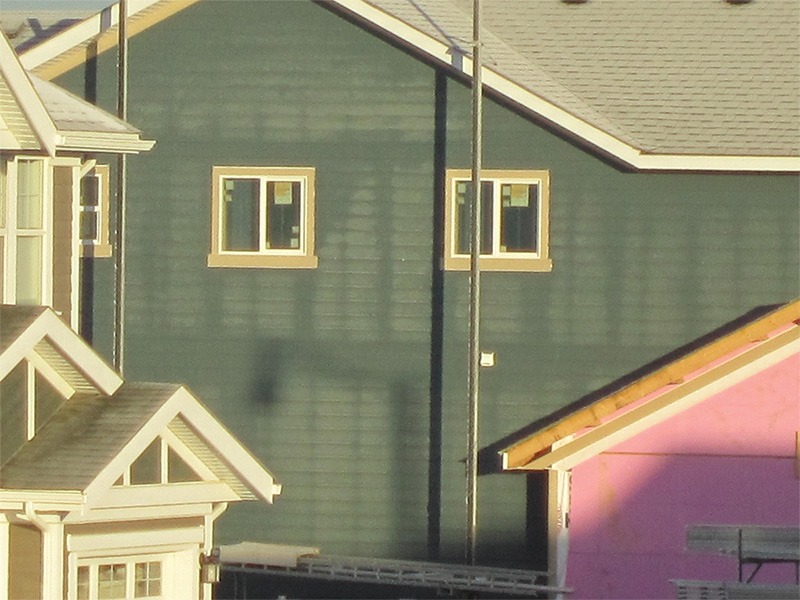
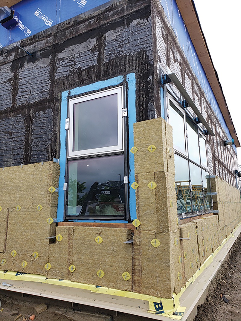
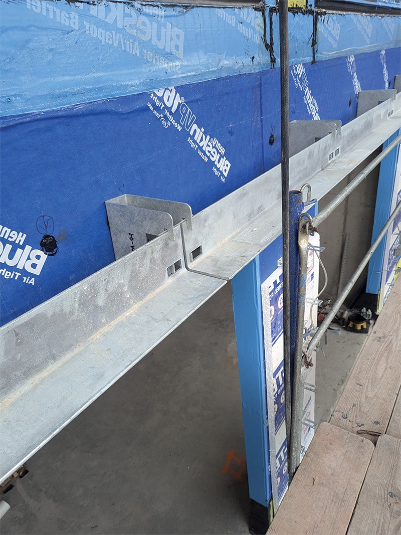
Thermal bridging is a very real phenomenon and can greatly reduce the thermal performance of a building envelope assembly. On a frosty day in Alberta, the dark areas located at the wood studs and floor rim boards on a wall in Figure 1 can be seen in stark contrast to the white frost between the studs, where the insulation is reducing heat loss on the home under construction. In these dark areas, the thermal bridging of the wood-framing has melted the frost, creating the look of dampness.
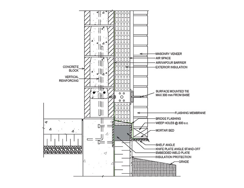
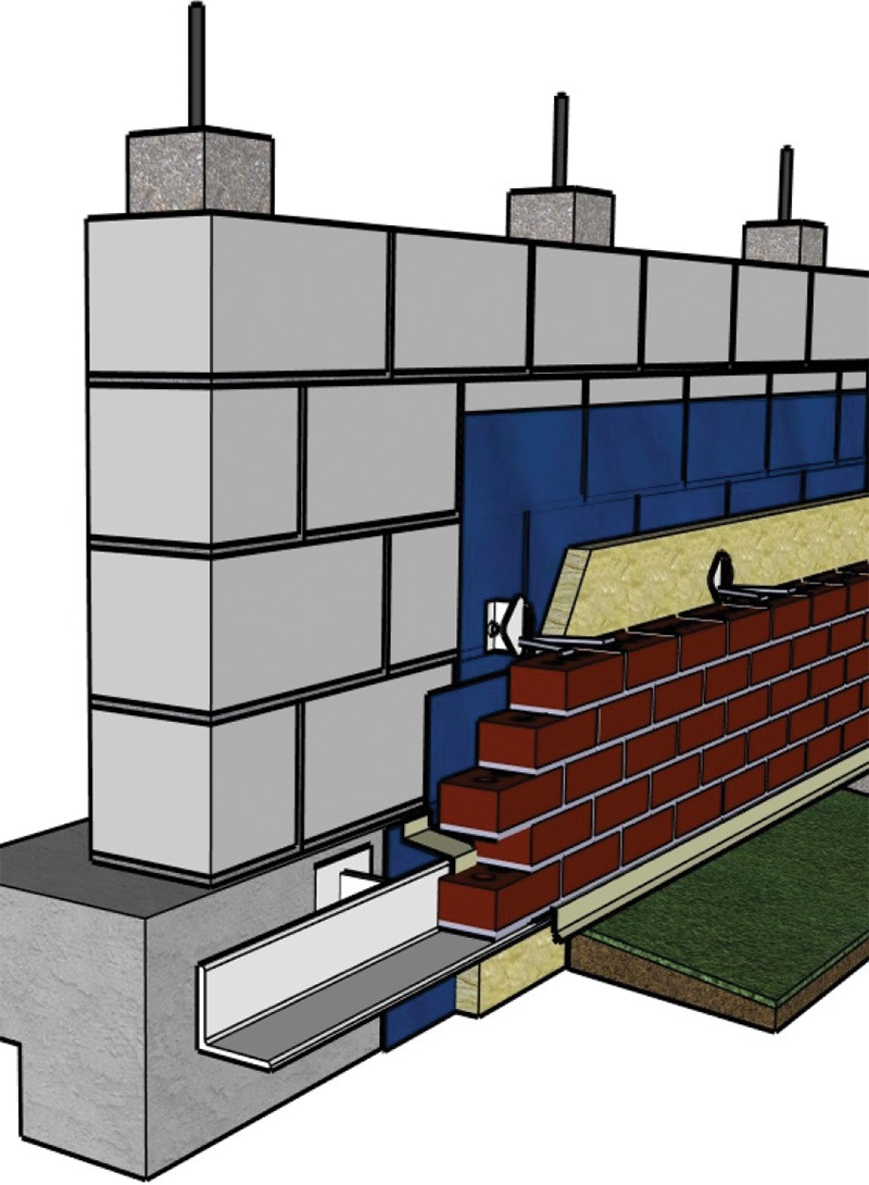
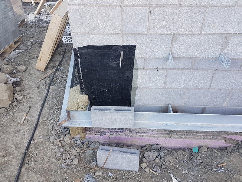
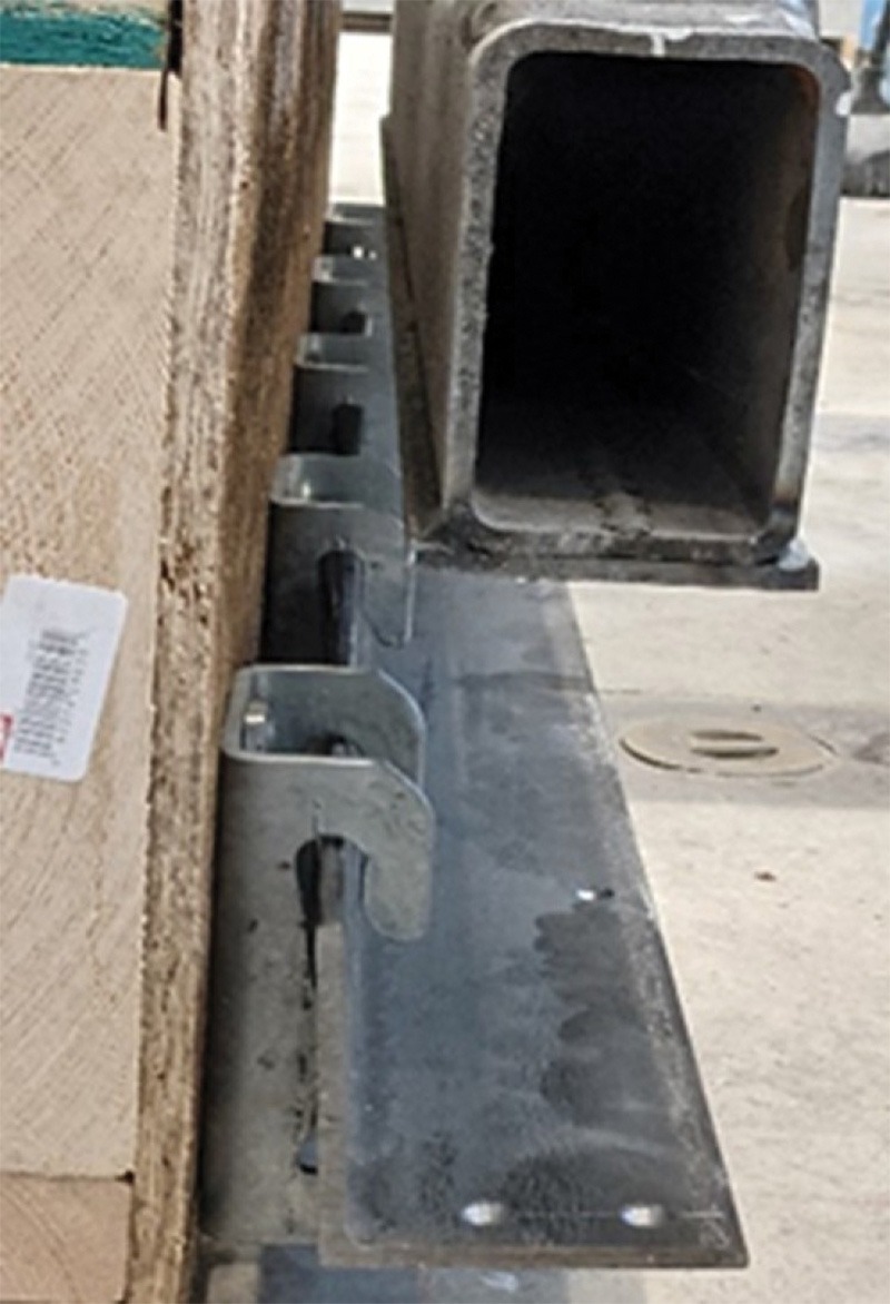
To become more thermally efficient, it is important to provide a break between thermal bridges. The use of continuous exterior insulation at above- and below-grade transitions of the wall and at floor and roof transitions has a significant impact on reducing thermal bridging in wall assemblies. For several years now, continuous insulation (c.i.) for masonry veneers has been achieved by placing shelf angles on insulation standoffs. A common method to create an insulation stand-off uses steel knife plates welded onto the shelf angle, which are then welded to concrete embed plates that are anchored to concrete foundations (or floors), as illustrated in Figures 2 and 3. This knife plate stand-off allows for insulation to be installed behind the shelf angle, providing c.i. above and below grade with insulation that is in direct contact with the backup wall.
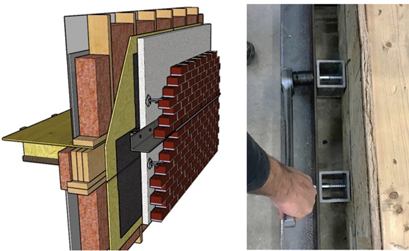
Alternatively, steel or fibre-reinforced polymer (FRP) hollow structural sections (HSS) stand-offs can be bolted to the structure to provide the space for the insulation to be installed behind the shelf angle, as illustrated in Figure 4.
Lastly, proprietary pre-engineered stand-off systems can also be used, as illustrated in Figure 5.
The advantage of the HSS sections or proprietary stand-offs is that they are bolted to the structure and can be installed by the mason. Bolting also avoids welding, which is advantageous when anchoring to wood structures.
Table 1: Test results of shelf angle on FRP HSS standoff on wood-frame floor
|
Test specimen |
Failure load
kN (lb) |
Deflection at failure
(mm) |
Factor of safety |
| Lag screw with 3 in. (76 mm) deep FRP HSS standoff -1 | 28
(6,292) |
37.7 | 3.5 |
| Thru-bolt with 3 in. (76 mm) deep FRP HSS standoff -1 | 28
(6,292) |
30 | 3.5 |
| Lag screw with 3 in. (76 mm) deep FRP HSS standoff -2 | 30
(6,742) |
43.8 | 3.8 |
| Thru-bolt with 3 in. (76 mm) deep FRP HSS standoff -2 | 49
(11,101) |
69 | 6.1 |
| Lag screw with 2 in. (51 mm) deep FRP HSS standoff -1 | 47
(10,562) |
41 | 5.9 |
| Thru-bolt with 2 in. (51 mm) deep FRP HSS standoff -2 | 72
(16,180) |
72.7 | 9.0 |
| *Shivam Sharma/University of Windsor | |||
Like shelf angles that are directly bolted to concrete or wood framing, the design of shelf angles on insulation stand-offs represents the intersection of masonry and steel design, and depending on the building’s primary structural system, concrete, steel, or wood design. Often regarded as a “steel” design or a “concrete” design problem, rather than a “masonry design” problem, very little research or design guidance is available for the design of shelf angles on stand-offs. As with directly bolted shelf angles, this often leads to the oversizing of shelf angles, insulation stand-offs, bolts, and embed plates for shelf angles when c.i. is being used.
Recent testing and research of shelf angles on stand-offs anchored to concrete foundations and wood framing have provided insight into the behaviour and structural capacities that can be expected from these systems.
This article provides examples and discusses testing and research results of masonry veneers on knife plate, HSS, and proprietary stand-offs. It will also discuss the resulting strategies for a more efficient design of steel shelf angles on knife plate stand-offs.
Testing results of HSS and proprietary stand-offs anchored to wood-frame floors
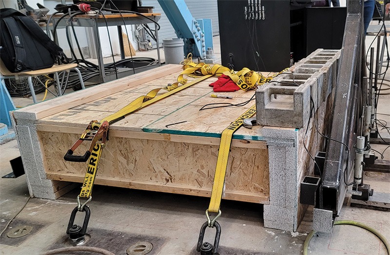
Shelf angles bolted to 102 mm (4 in.) long FRP HSS 76 x 76 x 6 mm (3 x 3 x 0.25 in.) and anchored to three-ply 2×12 spruce-pine-fir (SPF) rim boards on a wood-framed floor system were tested to failure at the University of Windsor between 2021 and 2023. Figure 6 illustrates the specimen being tested.
The mode of failure was either rotation or splintering of the SPF rim board, rather than lag screw or thru-bolt withdrawal. The results of the testing are found in Table 1.
The results presented in Table 1 indicate a safety factor ranging from 3.5 to 3.8 was achieved for 76 mm (3 in.) insulation stand-offs. For 51 mm (2 in.) insulation stand-offs, a safety factor of between 5.9 and 9 was obtained. This analysis assumes the weight of 3 m (10 ft) of brick veneer, which is approximately 7.99 kN (1,796 lb), is acting on the shelf angle mounted on the stand-off. This indicates 3 m (10 ft) of brick veneer can be safely carried by the FRP HSS systems. It is important to note that the cantilevering of the through-bolt or lag screw through the HSS section reduces the structural capacity of the system as compared to proprietary systems that directly bolt to the SPF rim board.
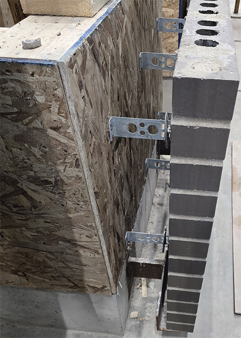
The test was repeated using a proprietary shelf angle stand-off. Once again, the proprietary stand-off and shelf angle were anchored to three-ply 2×12 SPF rim boards on a wood-framed floor system and taken to failure, as can be seen in Figure 7.
As with the FRP HSS stand-offs, the mode of failure was either rotation or splintering of the SPF rim board rather than lag screw or thru-bolt withdrawal. The results of the testing are found in Table 2.
Table 2: Test results of shelf angle on Fero-Fast Bracket standoff on wood-frame floor
| Test specimen | Failure load kN
(lb) |
Deflection at failure
(mm) |
Factor of safety |
| Lag screw specimen @ 12-in. (305-mm) o.c. Fero-Fast bracket-1 (without Fero shim) | 73
(16,404) |
28.1 | 9.2 |
| Thru bolt specimen @ 12-in. (305-mm) o.c. Fero-Fast bracket-1 (without Fero shim) | 102
(22,921) |
54.8 | 12.8 |
| Lag screw specimen @ 12-in. (305-mm) o.c.
Fero-Fast bracket-2 (with Fero shim) |
77
(17,303) |
44.7 | 9.6 |
| Thru bolt specimen @ 12-in. (305-mm) o.c. Fero-Fast bracket-2 (with Fero shim) | 83
(18,652) |
52.6 | 10.4 |
| *Aarish Khan/University of Windsor | |||
The results presented in Table 2 demonstrate safety factors ranging from 9.2 to 12.8 for 51 mm (2 in.) insulation stand-offs without a shim. For the proprietary stand-offs with a shim providing 76 mm (3 in.) insulation, safety factors ranging from 9.6 to 10.4 were observed. These calculations were once again based upon the assumption that a weight of 3 m (10 ft) of brick veneer, approximately 7.99 kN (1,796 lb), was acting on the shelf angle on a proprietary stand-off. This indicates that the proprietary systems can also safely support 3 m (10 ft) of brick veneer. Further, the ability to directly bolt to the SPF rim board using the proprietary system significantly enhances its structural capacity when compared to the cantilevered lag screws and through bolts used with the HSS stand-offs. The proprietary system more than doubles the capacity of the 76 mm (3 in.) specimen, achieving an ultimate load of 77 kN (18,652 lb), compared to the HSS system’s 30 kN (6,752 lb).
The conclusion is that either standoff system can be used with wood-frame floor systems to provide c.i. for shelf angles at floor transition locations in wood-frame buildings.
Testing results of steel knife plate stand-offs anchored to concrete foundations
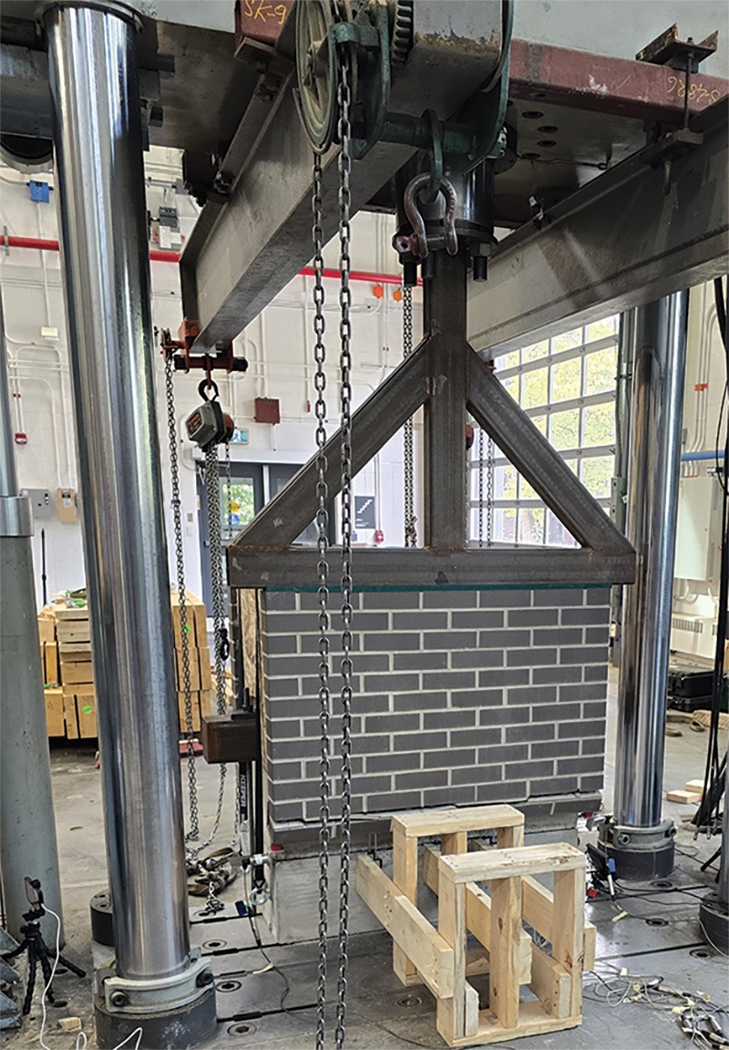
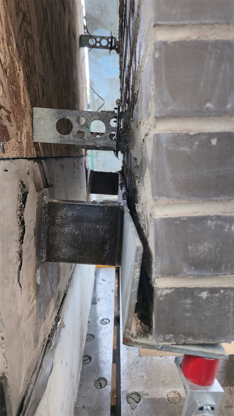
A 102 x 102 x 6 mm (4 x 4 x 0.25 in.) shelf angle welded onto 127 x 102 x 19 mm (5 x 4 x 0.74 in.) steel knife plate stand-offs that were anchored to embed plates on concrete foundations were tested to failure at the University of Alberta in 2025. In addition to using steel knife plates, stand-offs, and concrete structures, these tests also differed from the wood-floor tests in that the effects of the masonry ties and brick veneer on the deflection of the shelf angle were also explored as part of the research. The shelf angle on knife plates with masonry ties and brick veneer can be seen in Figure 8. An axial load of 15.17 kN (3,410 lb) was applied to the top of the 813 mm (32 in.) tall brick veneer (Figure 8), which delivered a total axial load equivalent to the weight of 7 m (24 ft) of clay brick veneer on the specimen. The deflection of the shelf angle on knife plates was then measured at this load. The results are found in Table 3.
The specimen was then taken to failure. Failure occurred at a load of 96.8 kN (21,708 lb), providing a factor of safety of 5.6. The ultimate failure resulted from tearing out of the embed plate, as can be seen in Figure 9.
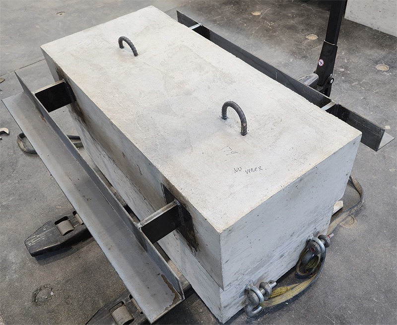
The effect of the masonry ties and brick veneer on shelf angle defection was investigated by conducting comparison tests that ignored the effects of the masonry ties. In these tests, the masonry tie and brick veneer effects were eliminated by applying a load of 17.08 kN (3,839 lb) to the bare shelf angle specimen, as can be seen in Figure 10. The test method was identical to those conducted on the wood-frame floors, which also ignored the effects of masonry ties and brick veneer by applying the load directly to the shelf angle.
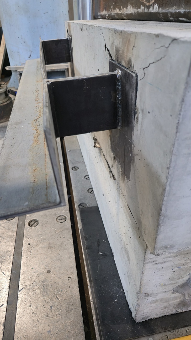
Failure of the specimen occurred at a load of 126.6 kN (28,449 lb). As with the shelf angle on knife plates with masonry ties and brick veneer, the ultimate failure resulted from the tear out of the embed plate, as can be seen in Figure 11. The results from the testing can be found in Table 3 for easy comparison.
Table 3: Test results of shelf angle on knife plate stand-offs
|
Load point
|
Shelf angle with brick and ties | Shelf angle only | ||
| Axial
load (kN) |
Shelf angle
deflection (mm) |
Axial
load (kN) |
Shelf angle
deflection (mm) |
|
| Weight of 7 m (24 ft) of brick | 15.17 | 0.6872 | 17.08 | 2.979 |
| Failure load | 96.84 | 23.99 | 126.6 | 34.3 |
| Factor of safety | 5.7 | 7.4 | ||
| *Cory Scott/University of Alberta | ||||
The testing demonstrated that with a service load (weight of 7 m [24 ft] of veneer) applied to the shelf angle on knife plate specimens with masonry ties and brick veneer, a deflection of 0.6872 mm (0.0271 in.) occurred. In contrast, the testing of the shelf angle on the bare knife plate experienced a significantly larger deflection at the service load of 2.979 mm (0.1173 in.) or about 433 per cent more deflection. These results demonstrate that the effects of the masonry ties and brick veneer are clearly reducing the deflection of the shelf angle and should not be ignored. However, the testing also demonstrated that a full moment connection between the shelf angle and the brick veneer when structurally analyzing the system may be too generous, as the deflection from testing is about 50 per cent more than the deflection predicted using a full moment connection. It appears the brick veneer shelf angle system would be better represented using a rotational spring at the brick veneer/shelf angle interface so that the deflection-reducing effects of the masonry ties on the shelf angle are better captured.
Design of knife plate stand-offs using the force method and virtual work
A new design approach that more accurately considers the interaction between the tied masonry veneer and the shelf angle is necessary to better capture the deflection-reducing effects of masonry ties and brick veneer on shelf angles with knife plate stand-offs that support masonry veneers. The proposed design method uses the force method in combination with virtual work to address the one-degree statically indeterminate system created by the introduction of the tie restraining force (RTIE) at the first course of ties, as illustrated in the free body diagram shown in Figure 12.
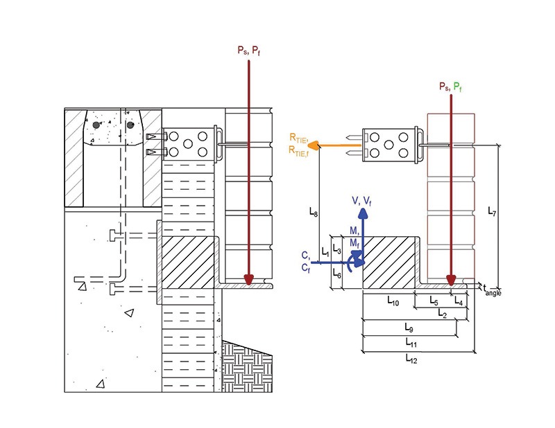
From Figure 12, the following parameters are required to use the force method and virtual work supporting 7 m (24 ft) of brick veneer:
- b = Knife plate spacing = 813 mm (32 in.)
- P = Unfactored (service load) of masonry veneer and shelf angle (N) = 11,506 N (2,586 lb)
- P_f = Factored load of masonry veneer and shelf angle (N) = 16,108 N (3,620 lb)
- RTIE = Reaction force in the brick ties at the first course of ties (kN)
- V_f = Reaction force in the brick ties at the first course of ties (kN)
- T_f = Reaction force in the brick ties at the first course of ties (kN)
- C_f = Reaction force in the brick ties at the first course of ties (kN)
- t_angle = Thickness of the horizontal leg of the angle = 7.9 mm (0.3 in.)
- L_knife = 127 mm (5 in.)
- b_knife = 19 mm (0.75 in.)
- h_knife = 102 mm (4 in.)
- t_veneer = Thickness of the masonry veneer = 92 mm (3.6 in.)
- t_airspace = 25 mm (1 in.)
- V-tie_radius = 2.4 mm (0.09 in.)
- L1 = Vertical leg length = 103 mm (4 in.)
- L2 = Horizontal leg length = 103 mm (4 in.)
- L3 = Vertical distance to the centre of the knife plate = 51 mm (2 in.)
- L4 = L2 – L5 = 30 mm (1.19 in.) for imperial modular brick
- L5 = Eccentricity of veneer load = Air space + veneer thickness/2 = 72 mm (0.28 in.)
- L6 = L1/2 = 51 mm (2 in.)
- L7 = Max 300 mm (12 in.) from base support = 278 mm (11 in.)
- L8 = Vertical distance between the ties and the centre of the knife plate = 228 mm (9 in.)
- L9 = Distance from vertical shelf angle to centroid of brick
- L10 = Length of the knife plate = 127 mm (5 in.)
- L11 = Distance from start of knife plate to centroid of brick = 199 (8 in.)
- L12 = Total horizontal distance = L_knife + t_airspace + t_veneer = 245 mm (10 in.)
- f’m = The compressive strength of the masonry veneer = 12 MPa (1,740 psi)
- Em = Modulus of elasticity of the masonry veneer = 850 f’m = 10,200 MPa (1.4 million psi)
- Es = Modulus of elasticity of structural steel = 200,000 MPa (29 million psi)
- I_angle = b ∙ t_angle^3 / 12 = 21,337 mm⁴ (0.013 in.⁴)
- I_knife = b_knife ∙ h_knife^3 / 12 = 1.6 million mm⁴ (1.01 in.⁴)
- I_veneer = b ∙ t_veneer^3 / 12 = 65 million mm4 (39.74 in.⁴)
- I_tie = 4 ∙ [π∙V-tie_radius^4 / 4] = 104 mm4 (0.00064 in.⁴)
To use the force method, the statically indeterminate structure was made determinate by the introduction of a release. In this case, the release chosen was at the tie and labelled co-ordinate 1 in Figure 13. The service load, P, and a unit load at co-ordinate 1, were then applied to the released (determinate) structure.
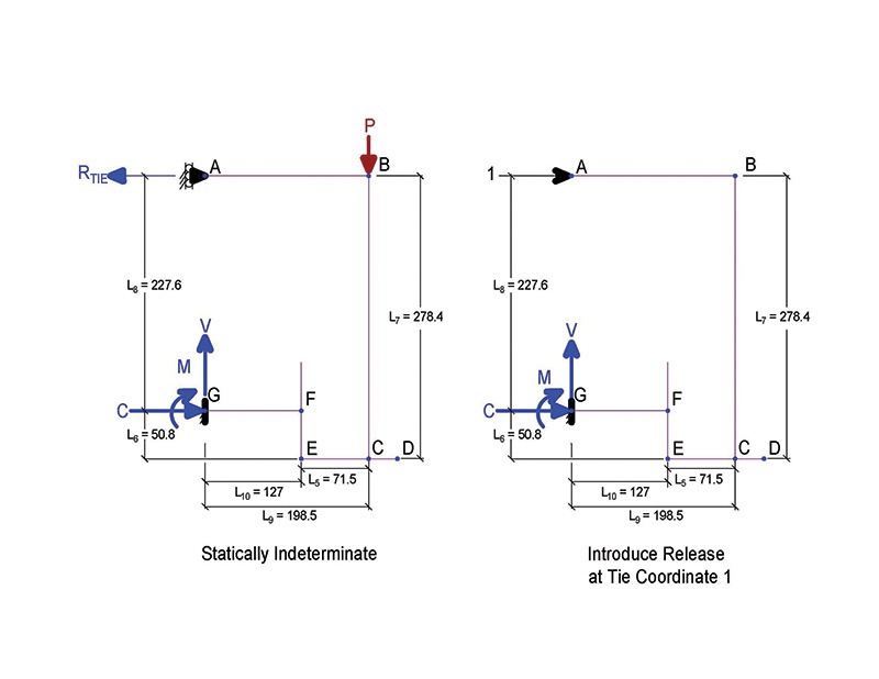
A partial moment connection, mimicking the introduction of a rotational spring at the brick veneer steel/shelf angle interface, was simulated by reducing Em to Em, effectively accounting for the reduced rotational stiffness at this interface. This partial moment connection reduces the tension load in the ties and increases the shelf angle deflection when calculated using the force method and virtual work. Em, effective was determined to be 1/100th of Em. This value for Em, effective, was calibrated based on the testing results from the University of Alberta, providing the same deflection of 0.6872 mm (0.0271 in.) at the 17.08 kN (weight of 7 m [24 ft] of brick veneer) on the shelf angle.
The proof of the following equations is beyond the scope of this paper but can be determined by applying the force method and virtual work to the free body diagram in Figure 13.
Once RTIE has been determined, virtual work is applied again to obtain the deflection at the tip of the shelf angle on the knife plate stand-off at Point D in Figure 13. Without proof, the equation is as follows:
Entering the numbers into these equations demonstrates a deflection of 0.46 mm (0.018 in.), which is less than the L/480 limit of 0.51 mm (0.02 in.).
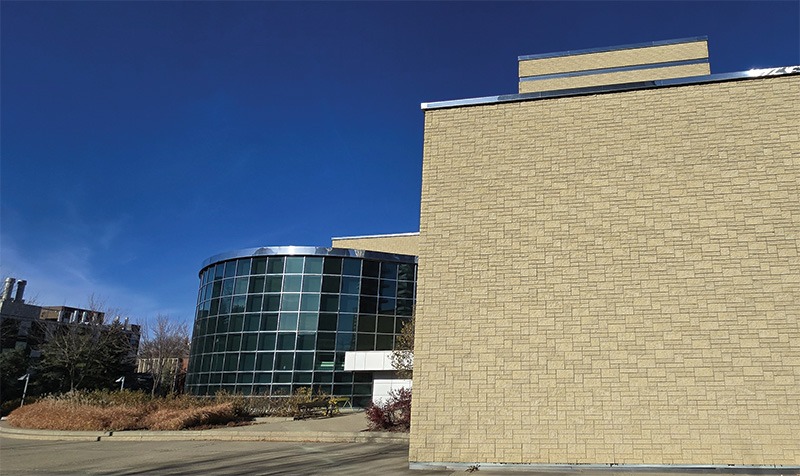
The testing results and design method proposed results in more efficient designs for both the shelf angle and the knife plates used as stand-offs to provide c.i. for full bed brick veneer installations and in this particular case permit installations of up to 7 m (24 ft) of brick veneer using a 102 x 102 x 7.9 mm (4 x 4 x 0.31 in.) shelf angle welded to 127 x 102 x 19 (5 x 4 x 0.75 in.) steel knife plate stand-offs, which are then welded to embed plates anchored in concrete foundations or floors. Past observations of this type of construction on a school used the same size knife plates, same knife plate spacing, and same shelf angle size to support 4 m (14 ft) of masonry veneer 3 m (11 ft). Applying the new design method suggests that with the same knife plate spacing of 813 mm (32 in.) o.c., the knife plate thickness could be reduced from 19 mm (0.75 in.) to 15.9 mm (0.63 in.), and the shelf angle size thickness could be reduced from 102 x 102 x 7.9 mm (4 x 4 x 0.31 in.) to 10 2x 102 x 6.4 mm (4 x 4 x 0.25 in.) and still be sufficient to support 4 m (13 ft) of veneer.
Optimizing the shelf angle design leads to smaller shelf angles and knife plates, which not only reduces costs but also enhances thermal performance and decreases the system’s carbon footprint.
Author

Mark D. Hagel, PhD, P.Eng., is the executive director of the Alberta Masonry Council. He holds a bachelor of science in actuarial science and applied mathematics, a bachelor of science in civil engineering, and a doctor of philosophy in civil engineering. Hagel’s fields of expertise include thermal and hygrothermal modelling of building systems, corrosion modelling, life cycle cost analysis, structural analysis and design, and the durability of building components. In 2018, Hagel served on the National Research Council of Canada’s (NRC’s) working group that developed the Guideline on Design for Durability of the Building Envelope and in a working group on the CSA-S478-2019 Durability in Buildings. He can be reached via e-mail at markhagel@albertamasonrycouncil.ca.
Sign up for our weekly newsletter
Construction Canada weekly newsletters give the latest AEC industry news for those who build, design, engineer, specify, renovate or operate in the built environment.
Products & Services


Read the Latest Issue