Quality assurance of post-installed anchors in CSA A23.3-24
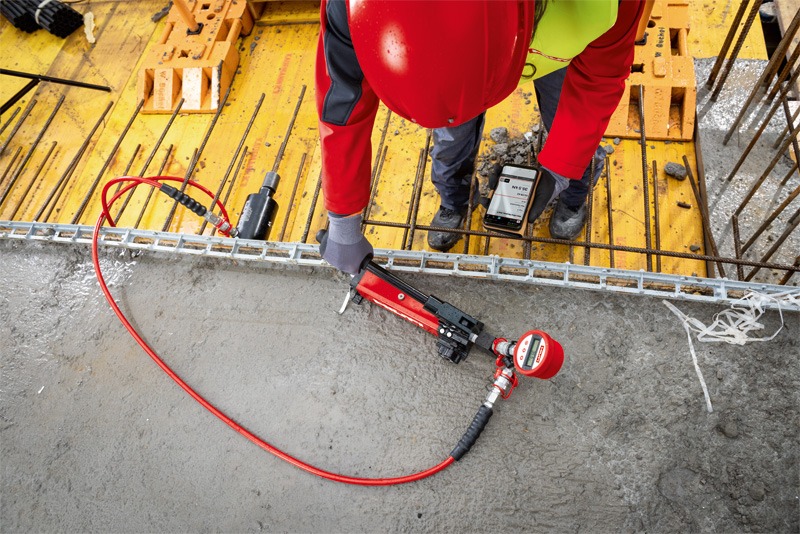
Post-installed anchors and post-installed reinforcing bars are widely used in structural and non-structural applications such as equipment anchorage, structural steel connections, and strengthening or modification of existing concrete structures. Achieving the published performance of post-installed connections depends on proper installation.
For this reason, Canadian Standards Association (CSA) A23.3-24 includes specific quality assurance (QA) requirements for post-installed anchors and post-installed reinforcing bars. Clause D.10.2 establishes inspection requirements intended to ensure that anchors are installed in accordance with the approved contract documents and manufacturer’s published installation instructions (MPII).
Quality assurance for post-installed anchors generally includes:
- Special inspection during installation in accordance with CSA A23.3-24 Clause D.10.2 and Table D.3
- Proof load testing for certain adhesive anchor applications in accordance with Clause D.10.2.2.2
This article provides an overview of CSA A23.3-24 requirements and illustrates how proof loads for adhesive anchors can be determined.
Inspection requirements in CSA A23.3-24
Clause D.10.2.1 of CSA A23.3-24 specifies that the minimum level of inspection for post-installed anchors and post-installed reinforcing bars shall be in accordance with Table D.3, as shown in Table 1 at right.
Inspection must be performed by a third-party inspector, as defined in CSA A23.3, a person employed by the owner or the owner’s representative who has the competence necessary to inspect a particular type of construction.
CSA A23.3 distinguishes between two types of inspection for anchors and post-installed reinforcing bars:
- Continuous special inspection—Inspection performed by a third-party inspector who is present when and where the work being inspected is performed.
- Periodic special inspection—Inspection performed by a third-party inspector who is intermittently present during the work.
Table D.3 specifies the required inspection level depending on anchor type and loading conditions.
CSA A23.3-24 also references American Concrete Institute (ACI) 355.4-19(21) for the qualification of post-installed adhesive anchors. In addition to qualification testing requirements, ACI 355.4-19(21) provides guidance on inspection procedures for adhesive anchor installation.
According to ACI 355.4-19(21) Clause 13.3.2, the special inspector should observe all aspects of anchor installation. As a minimum, the inspector should verify the following items:
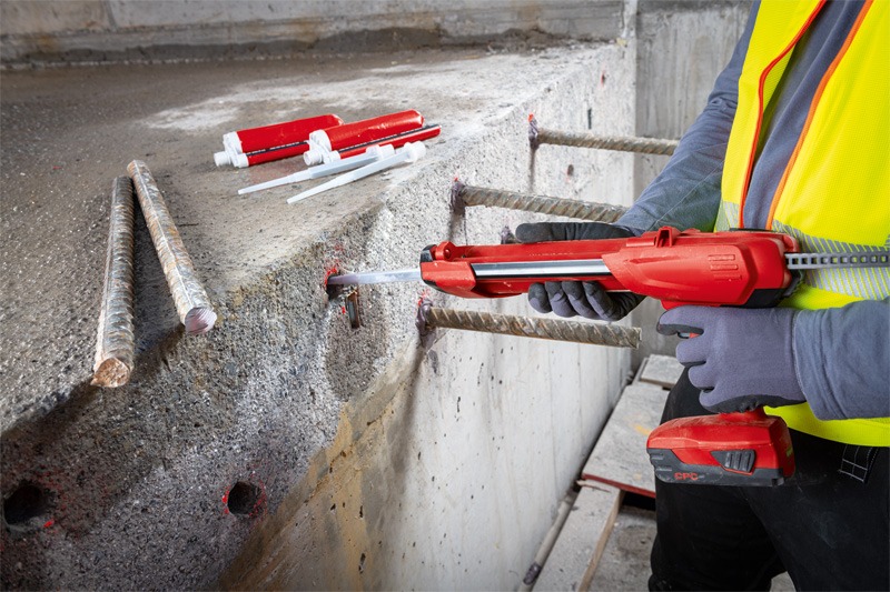
- Hole drilling method in accordance with the manufacturer’s published installation instructions (MPII).
- Anchor edge distance and spacing in accordance with the contract documents.
- Hole diameter and depth.
- Hole cleaning procedures in accordance with the MPII.
- Anchor element type, material, diameter, and length.
- Adhesive identification and expiration date.
- Adhesive installation procedures in accordance with the MPII.
ACI 355.4-19(21) Clause 13.3.2 further clarifies that under continuous special inspection, holes may be drilled in the absence of the special inspector, provided that the inspector subsequently verifies the drill bits used and confirms the hole diameter. This allowance is specific to continuous inspection and differs from periodic inspection, in which the initial installation of each type and size of adhesive anchor by construction personnel on site must be observed and verified.
| Type | Continuous special inspection and proof loading | Periodic special inspection |
| a) Adhesive anchors and post-installed reinforcing bars installed in horizontally or upwardly inclined orientations to resist sustained tensile loads | X | – |
| b) Adhesive anchors and post-installed reinforcing bars not defined in a) | – | X |
| c) Mechanical anchors | – | X |
Table 1—Minimum required special inspection for anchors and post-installed reinforcing bars (CSA A23.3-24 Table D.3).
Inspection-related proof load testing of adhesive anchors
When continuous special inspection is required for adhesive anchors, CSA A23.3-24 Clause D.10.2.2.2 requires additional proof load testing.
For the purposes of continuous inspection with proof loads determined in accordance with CSA A23.3-24, proof load testing provides additional verification of anchor installation quality and proper adhesive bond development. It is not intended to determine the ultimate strength of the anchor.
Clause D.10.2.2.2 specifies that proof loading shall:
- Be conducted in a confined test setup in accordance with ASTM E3121, Standard Test Methods for Field Testing of Anchors in Concrete or Masonry.
- Maintain the required load for a minimum of 10 seconds.
The proof load level, Nproof, is required to be the lesser of the bond-based limit, Nbond,proof and the steel-based limit, Nsteel,proof, as defined below.
Bond-based limit
The proof load based on adhesive bond resistance is determined as 67 per cent of the characteristic bond resistance associated with uncracked concrete, including applicable adjustments for edge distance and concrete strength in accordance with CSA A23.3-24 Clause D.10.2.2.2(a).
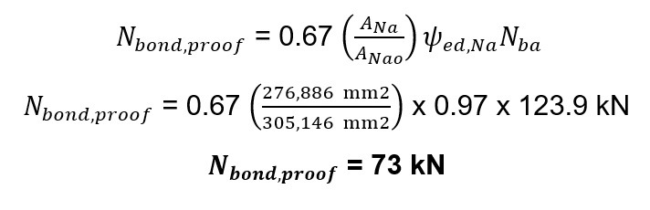
The proof load, Nbond,proof, may be calculated as:
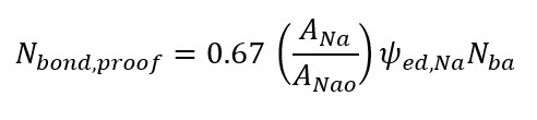
where:
Nba= characteristic bond resistance of a single adhesive anchor in uncracked concrete, introduced herein for clarity, and obtained by dividing the factored bond resistance Nbar in CSA A23.3-24 Clause D.6.5.2 by the concrete material resistance factor Φc and resistance modification factor R; this symbol is not explicitly defined in CSA A23.3-24.
ANa= projected influence area of an adhesive anchor or group of adhesive anchors, considering edge effects.
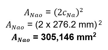
ANao= projected influence area of a single adhesive anchor, for calculation of bond strength in tension if not limited by edge distance or spacing.
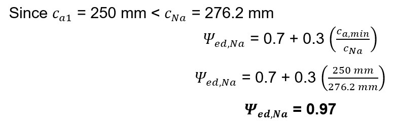
- Ψed,Na= modification factor accounting for edge distance effects.
Important note
For proof load testing, bond resistance should be determined for the individual anchor being loaded. Group effects between anchors are not considered when establishing the proof load.
Steel-based limit
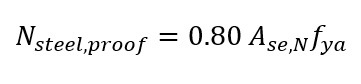
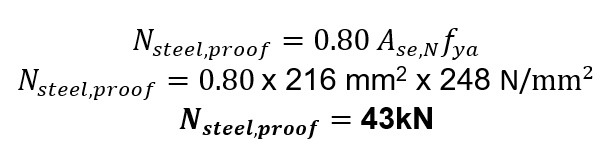
As stated in CSA A23.3-24 Clause D.10.2.2.2(b), the proof load shall also not exceed 80 per cent of the minimum specified yield strength of the anchor steel, Nsteel,proof, calculated as:
where:
Ase,N= effective cross-sectional area of anchor in tensionfya= specified yield strength of anchor steel.
This approach ensures the proof load is sufficiently high to verify installation quality while avoiding yielding the anchor steel or damaging the adhesive bond mechanism. A CSA A23.3-24 Note to Clause D.10.2.2.2 also states that proof load testing should not be used as a substitute for special inspection.
a. Determination of proof load example
The following simplified example illustrates the determination of the proof load in accordance with CSA A23.3-24 Clause D.10.2.2.2.
Given
Loads
Factored axial tension load: Nf = 25 kN (5,620 lbf)
Factored shear load: Vf = 35 kN (7,868 lbf)
Base plate dimensions
Base plate size: 300 x 300 mm (11.8 x 11.8 in.)
Base plate thickness: tbp = 12.7 mm (0.5 in.)
Anchor properties
Quantity of anchors: 4 (Example values shown are based on a commercially available adhesive anchoring system.)
Post-installed hybrid adhesive anchoring system with ASTM F1554 Grade 36 threaded rods, da = 19.1 mm (¾ in.)
Anchor effective area Ase,N = 216 mm2 (0.34 in.2)
Specified yield strength of anchor steel = fya = 248 N/mm2 (35,969 psi)
Anchor effective embedment: hef = 130 mm (5.11 in.)
Cracked concrete bond stress: τcr = 9.02 N/mm2 (1,308 psi)
Uncracked concrete bond stress: τuncr =
15.89 N/mm2 (2,305 psi)
Edge distance: Ca1 = 250 mm (9.9 in.)
Anchor spacing in both directions: s = 200 mm (7.9 in.)
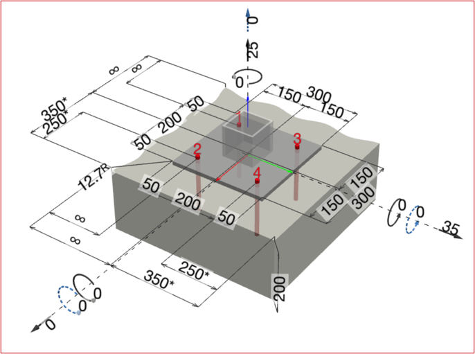
Concrete properties
Normal weight concrete: λa = 1
Compressive strength: fcl = 25 N/mm2 (3,626 psi)
Cracked concrete
Supplementary reinforcement Condition B (No anchor reinforcement or supplementary reinforcement to mitigate breakout)
Concrete thickness: ha = 200 mm (7.9 in.)
I. Bond-based limit calculation
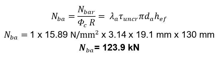
Calculation of Nba in accordance with Eq. D.25 from CSA A23.3-24:
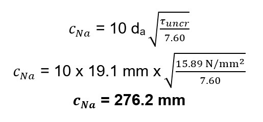
Calculation of CNa in accordance with Eq. D.24 from CSA A23.3-24
Calculation of ANao in accordance with Eq. D.23 from CSA A23.3-24:
Calculation of ANa for a single anchor in accordance with Clause D.6.5.1 from CSA A23.3-24: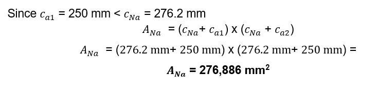 Calculation of Ψed,Na in accordance with Clause D.6.5.4 from CSA A23.3-24:
Calculation of bond-based proof load in accordance with Eq. D.21 from CSA A23.3-24:
II. Steel-based limit calculation
III. Governing proof load calculation
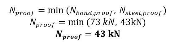
Therefore, the proof load applied for quality assurance purposes would be approximately 43 kN (9667 lbf), maintained for at least 10 seconds in a confined test setup, in accordance with ASTM E3121 requirements as specified in CSA A23.3-24 Clause D.10.2.2.2.
b. Key considerations for proof load testing
When specifying proof load testing for adhesive anchors, several considerations should be taken into account:
- Proof load testing is conducted on individual anchors, even if the anchor is part of a group. Accordingly, the proof load should be based on the bond resistance of a single anchor without considering group effects between anchors.
- Proof loading should only be performed after the adhesive has fully cured in accordance with the MPII.
- Testing must follow the confined test setup requirements of ASTM E3121, as referenced in CSA A23.3-24 Clause D.10.2.2.2.
- An independent, qualified third party should properly calibrate testing equipment. The testing program and required parameters should be defined in the contract documents in accordance with CSA A23.3-24 Clause D.10.2.2.3.
- Testing should be conducted by qualified personnel under the supervision of the inspector.
- A remediation plan should be established in the contract documents if failure of the anchor or surrounding concrete is observed during proof load testing or if there is failure to meet the required proof load. The licensed design professional should determine the remediation plan. It may include increasing the percentage of tested anchors within the job, evaluating the affected anchor, replacing the anchor, or installing additional anchors as required.
- Proof loading verifies installation quality but does not replace special inspection requirements.
For further discussion on special inspection and proof loading, refer to the references listed below.
References
- American Concrete Institute, ACI CODE-355.4: “Qualification of Post-Installed Adhesive Anchors in Concrete and Commentary,”American Concrete Institute, 2025, concrete.org/store/productdetail.x?ItemID=3554U19&Language=English&Units=US_Units
- Concrete and Masonry Anchor Manufacturers Association, “Special Inspection Guidelines for Post-installed Anchors and Fasteners,” Concrete and Masonry Anchor Manufacturers Association, 2025, chrome-extension://efaidnbmnnnibpcajpc glclefindmkaj/https://assets.noviams.com/novi-file-uploads/cama/PDFs_and_Documents/CAMA_Special_Inspeciton_Guidlines.pdf
- CSA Group. (2024). CSA A23.3, “Design of concrete structures,”2024, csagroup.org/store/product/CSA_A23.3:24/?srsltid=AfmBOoop9P7uvBSCGUft_lqMfbXIxX1FzR-BviWXBnTrdDQlBBbxSMFx
- Mattis, L., & Silva, J., “Inspecting Adhesive Anchors,” Concrete International, 59-64, May 2017, concrete.org/publications/internationalconcreteabstractsportal.aspx?m=details&ID=51700810
Author

Ali Ahrabi graduated with a bachelor’s degree in civil engineering in 2006 and obtained his master of science in civil engineering from Concordia University in 2012. He has been a professional engineer in the province of Quebec (Ing.) since 2013 and has experience in various engineering settings. Ahrabi currently serves as the manager of codes and approvals at Hilti Canada. He can be reached at ali.ahrabi@hilti.com.
Sign up for our weekly newsletter
Construction Canada weekly newsletters give the latest AEC industry news for those who build, design, engineer, specify, renovate or operate in the built environment.
Products & Services

Read the Latest Issue