The hidden cost of poor firestop specifications
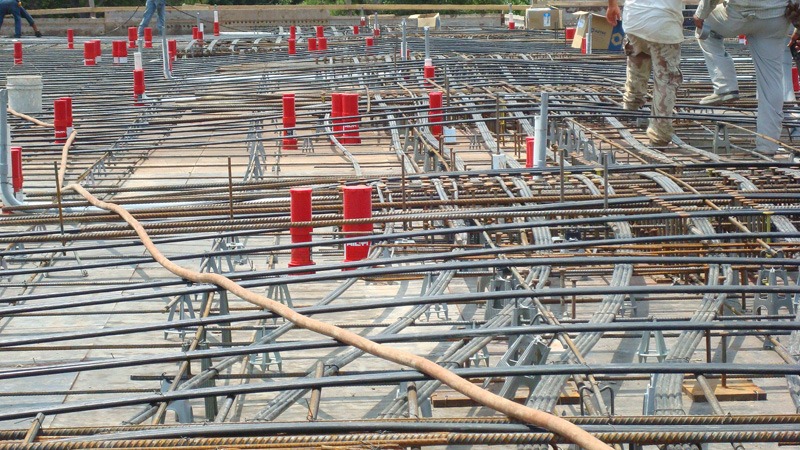
Firestop systems play a critical role in passive fire protection, preventing the spread of fire, smoke, and toxic gases through required penetrations and joints in fire separations. Despite that importance, they remain misunderstood by many engineers, architects, and specification writers. As a result, firestop specifications frequently fail to provide the direction and details necessary to achieve consistent, effective, and code-compliant installations.
Poor firestop specifications can affect almost every aspect of a project, including:
- Construction costs
- Project schedules
- Inspection outcomes
- Building code compliance
- Long-term building maintenance
- Fire and life safety performance
This is an overview of specification improvements that can affect one or more of the variables mentioned above. The focus will be on those improvements that will prevent the most common problems.
Before learning to run together, it is important to be sure that everyone can walk. Here is some general advice to help improve firestop specifications.
Firestopping is a system, not a product
One common shortcoming in Canadian specifications is language requiring the use of a “firestop sealant” or “approved firestop product” without emphasizing the need for tested and listed firestop systems. This distinction is critical. The National Building Code of Canada (NBCC) does not require firestop products. The NBCC definition of firestop is “a system” (Section 1.4.1.2). The code requires penetrations and joints in fire separations to be protected in a manner that fully maintains the assembly’s required fire-resistance rating and does not create any weak point for the spread of fire or smoke. Firestop products achieve that performance only when installed as part of a tested and listed system.
The NBCC sections covering each type of penetration or joint firestop mandate that each installed system must have been “subjected to the fire test method in CAN/ULC-S115…” (Section 3.1.9.1). In the case of the curtain wall perimeter gap, firestopping must be “subjected to the fire test method in ASTM E2307…” (Section 3.1.8.3.[4]). Canadian fire test listings in accordance with these standards are primarily maintained by Standards Council of Canada (SCC)-accredited organizations, UL Solutions and Intertek.
Would an improved specification solve the problem by including a selection of systems that might have been used on a previous project? Unfortunately, no.
A search of the UL Solutions “Product iQ” online listing directory (UL.com/PIQ) reveals that the following number of firestop systems are certified for Canada: (UL designation for each category is in parentheses)
- Through penetrations = 5,915 systems (XHEZ7)
- Joints = 2,005 systems (XHBN7)
- Perimeter fire containment systems (curtain wall firestopping) = 244 systems (XHDG); Intertek has an approximately equivalent or greater number of systems as well.
The reason there are thousands of systems is that each one is typically tested and listed for a very narrow set of conditions. Each system limits its applicability to a unique combination of:
- The exact type of wall or floor assembly
- Fire-resistance rating
- Penetrant materials
- Penetrant diameters
- Insulation types and thicknesses
- Opening dimensions
- Joint size
- Specific firestop products
All of this makes it clear that every single variable matters.
Changing one variable often requires selecting an entirely different system. Therefore, selecting a few listed firestop systems that might be “typical” for purposes of a specification is unlikely to provide the actual systems to be installed that will comply with the NBCC requirement for each firestop to be installed as tested.
To improve system selection, specifiers should use manufacturer system-selection tools (web or smartphone apps), engage manufacturer technical representatives on larger projects, or require a qualified firestop specialty contractor for penetration and joint firestopping.
Because firestop listings are highly application-specific, copying firestop specifications from previous projects results in systems that do not match actual field conditions, leading to non-compliant installations, rework, delays, and added costs.
The future of firestop specifications should focus on providing a list of selected, tested systems that should meet the known, specific needs of each project. Merely identifying acceptable products serves no purpose.
Why “or equal” can be problematic
Generic “or equal” clauses are common throughout construction specifications. Firestopping is different. Firestop performance depends on tested system configurations, as strictly required by the NBCC. Substituting individual products without verifying that the replacement products have been tested for each required application could leave the job without any path to code compliance, except perhaps through the lengthy and uncertain process of seeking approval of firestop technical evaluations (TEs) (historically referred to as “engineering judgments”). Specifications should therefore require that substitutions demonstrate equivalency at the system level, not simply at the product level. Seemingly similar products do not necessarily create equivalent firestop systems. This distinction is especially important when substitutions occur after permit approval, during procurement, or in response to supply chain disruptions.
With the “motherhood and apple pie” advice above out of the way, this article will now focus on a few very common, specific firestopping problems that could readily be prevented and solved with some specific specification inclusions.
Combustible pipe firestopping: where projects go wrong
Poorly planned or completely unplanned combustible pipe firestopping is probably the most common cause of unnecessary costs and delays.
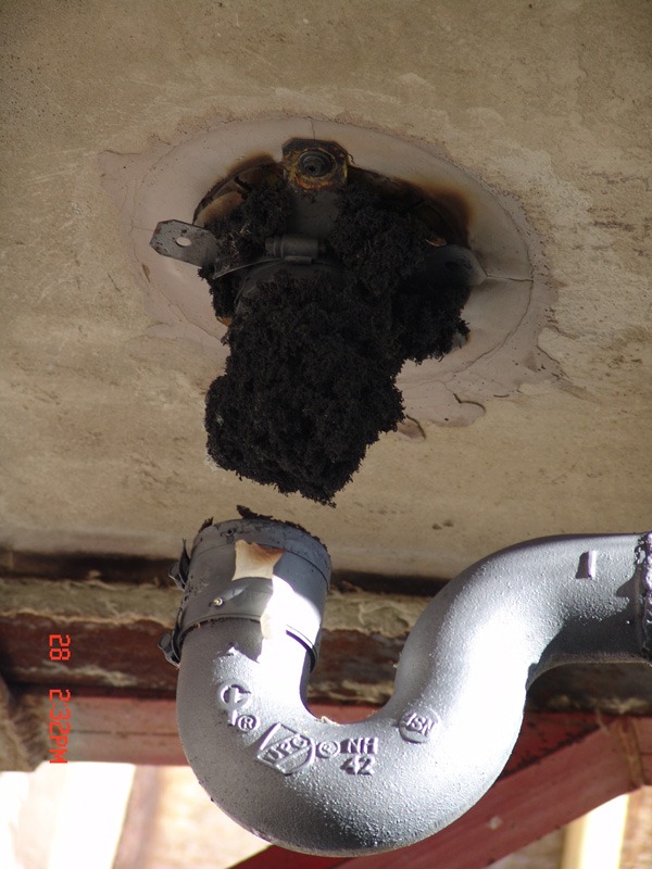
Combustible pipes, especially those over 50 mm (2 in.) in diameter, require a specific type of firestopping. That type is “intumescent” firestopping, which involves the use of sealants or strips that will expand when exposed to the heat of a fire. That expansion will need to crush and close the melting or burning pipe, thus closing off the pipe and preventing the spread of fire across the fire separation. See Figure 1 for an example of intumescent action that seals a pipe.
Allowing that intumescent expansion to do its job requires each firestop system to be installed very precisely.
The firestopping options for combustible pipes are as follows:
- Intumescent sealant (caulk) within the annular space of the penetration
- Intumescent “tuck strips” which are tucked into the annular space between the pipe and the opening in the fire separation
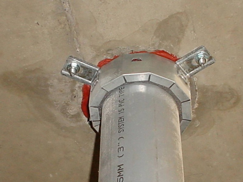
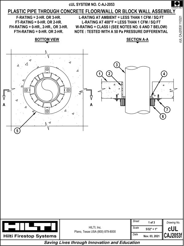
- Metal collar fastened to the assembly containing the intumescent strips.
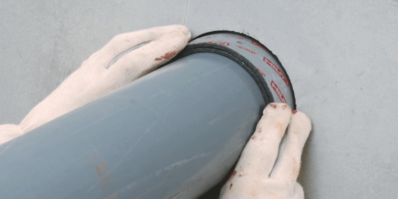
The images below illustrate the tuck strip (wrap strip) and collar options.
Hole size control
This very common problem that prevents combustible pipe firestopping from being installed quickly and economically is having a hole size in the substrate that does not match the minimum and maximum hole sizes allowed by the referenced (or any) tested firestop system.
Firestopping a hole whose size and shape do not correspond to the best (or any) tested penetration firestop systems will result in unnecessary time, costs, and aggravation. To prevent that, it would be wise for the specification to add the following hole-size requirements to CSC/CSI MasterFormat Division 22 00 00—Plumbing and Division 23 00 00—HVAC for penetrations of fire separations.
- a)Pipes nominal 50 mm (2 in.) and smaller:
- Optimal hole or sleeve diameter: 16 mm (0.625 in.) larger than actual pipe diameter.
- Maximum hole or sleeve diameter: 32 mm (1.25 in.) larger than pipe. This maximum already provides fewer firestop options than a hole that would be the optimal 16 mm (0.625 in.) larger than the pipe.
- b) Pipes larger than nominal 50 mm (2 in.), where a “tuck-in” wrap strip firestop solution is desired.
- c) The hole sizes should follow this table:
| Nominal pipe diameter | Maximum diameter of opening |
| 30 mm (1.2 in.) | 76 mm (3 in.) |
| 50 mm (2 in.) | 89 mm (3.5 in.) |
| 75 mm (3 in.) | 102 mm (4 in.) |
| 75 mm (3 in.) where the tested system requires 2 layers of wrap strip |
127 mm (5 in.) |
| 100 mm (4 in.) | 152 mm (6 in.) |
- d) Pipes larger than nominal 50 mm (2 in.), where a firestop collar solution is desired.
The hole sizes should be no more than 25 mm (1 in.) larger than the actual pipe diameter.
If the hole size is unfortunately too large, some systems provide a “rescue” option: using a sheet-metal cover plate, minimum 18-gauge, retrofitted and attached over the opening before attaching a firestop collar. See Figure 4 for an example of such a firestop system.
This involves multiple additional time- and material-consuming steps that would not be required if the hole size were properly matched to the pipe diameter. Even this system has limitations on the hole size. If the hole is non-circular or far too large, there might not be any tested system that meets field conditions. In that case, the project will incur the additional time and aggravation of seeking a technical evaluation (TE) from the firestop manufacturer for the non-tested condition, and then navigating the approval process to obtain approval from the authority having jurisdiction (AHJ). In some cases, partial reconstruction of the wall to create an opening with the proper size and shape is a perfectly acceptable solution. Doing so should allow the selection and installation of a tested and listed firestop system. However, oversized or irregular openings are often discovered only after wall construction and piping installation are complete, making reconstruction difficult, disruptive, and costly. For that reason, retrofit-type solutions, where available within the limitations of a tested system, are often the preferred approach.
Pipe spacing requirements
Intumescent solutions that wrap around a combustible pipe to seal it during fire exposure need some clearance for the intumescent materials to be positioned between adjacent pipes in the same hole.
- Space combustible pipes 50–75 mm (2–3 in.) apart within one large hole containing all of them, or preferably specify that the pipes should be within individual holes separated by this minimum distance.
Angled penetrations
A combustible pipe must enter and exit a fire separation at a 90-degree angle for it to be firestopped. There are no listed firestop solutions in Canada for a combustible pipe exiting a fire separation at an angle.
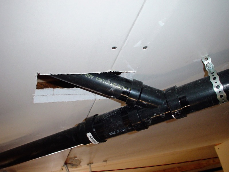
Angled pipe penetrations are most commonly the result of plumbers’ improvisation. Piping is normally specified, designed, and expected to penetrate any wall or floor at right angles to the surface.
- Provide a specification (e.g. in Division 22 00 00) that all pipe penetrations of fire separations must be at a right angle to the fire separation (wall or floor).
Where the specification clearly requires perpendicular penetrations, an angled combustible-pipe penetration should preferably be corrected by redoing the piping to comply with that requirement. In practice, however, many existing specifications do not expressly address penetration angle. When an angled penetration is discovered under those circumstances, the project team must determine whether a compliant alternative can be developed and accepted.
Where a pipe penetrates at an angle, the firestop manufacturer will, at best, propose a technical evaluation (TE) that must be submitted to and approved by the authority having jurisdiction (AHJ), which can cause delays.
A commonly proposed TE for such situations involves building a fire-rated gypsum box around the pipe penetration site, and then firestopping a perpendicular penetration through the gypsum box. However, because such solutions lack any known listed systems for reference, some manufacturers will refuse to issue such TEs, and some AHJs refuse to accept them.
Pipe elbows at fire separations
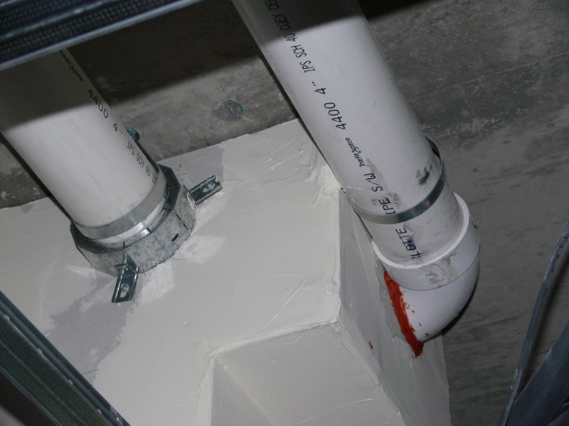
In a similar vein, there are no listed systems for a pipe elbow in or near the plane of a wall. See Figure 6 for examples of both a properly firestopped combustible pipe, using an intumescent collar, and of a pipe that cannot be firestopped due to an elbow at the plane of the wall, with no space for a collar. Where the specification clearly requires a perpendicular, unobstructed penetration with sufficient clearance for the selected firestop system, piping that does not meet those conditions should preferably be corrected.
Emerging pipe and insulation materials
Emerging pipe materials and insulation systems may not yet have any corresponding listed firestop systems. Because firestop testing and certification typically lag behind product innovation, specifiers should verify system availability during design rather than during construction. Where listed systems do not exist, TE and AHJ approvals may be required, creating schedule risk.
- For firestopping of emerging piping and insulation materials, select firestop systems early, or request a TE for AHJ approval.
Modern firestop technologies
Joint and penetration firestopping of the 1970s through 1990s consisted mostly of stuffing the open gap with compressed mineral wool, and then using an appropriate elastomeric, silicone-based, or intumescent sealant of the appropriate depth, or using intumescent strips and collars for combustible pipe penetrations. Since then, the firestopping industry has invested greatly in innovations that make installation faster, easier, more mistake-proof, and less dependent on installer experience and skill. It can be almost guaranteed that the plumbing, electrical, interior finishing, insulation, or mechanical contractor’s labourers will have little to no experience with firestopping. Nevertheless, those same contractors are expected—or at least hoped—to deliver code-compliant firestopping for the components they install in a building. One solution is to specify that all firestopping be contracted to a firestop specialty contractor, who will have expertise in both system selection and installation.
Since the 2000s, knowledgeable builders, developers, and contractors have increasingly turned to pre-formed firestop solutions. These products, when used within their listing parameters, provide firestopping for penetrations and joints that are fast and easy to inspect and install. General categories of 21st-century firestop solutions and their respective applications are
as follows:
- Cast-in-place firestop devices (sleeves) for combustible and non-combustible piping penetrations through concrete floors (flat deck and corrugated deck) (see Figure 7).
- Drop-in firestop sleeves for cored holes in concrete decks
- Foam-like intumescent firestop plugs for cable penetrations
- Foam-like intumescent firestop blocks for large rectangular openings, often used for multiple different penetrating items (see Figure 8).
- Cable sleeve devices (cable pathway devices), both modular/nestable and individual, for penetrations by cable bundles (see Figure 9).
- Pre-formed joint firestopping (see Figure 10).
Although pre-formed firestop devices generally cost more than traditional sealant-based solutions, labour savings, reduced installation errors, and faster inspections often lower total installed costs.
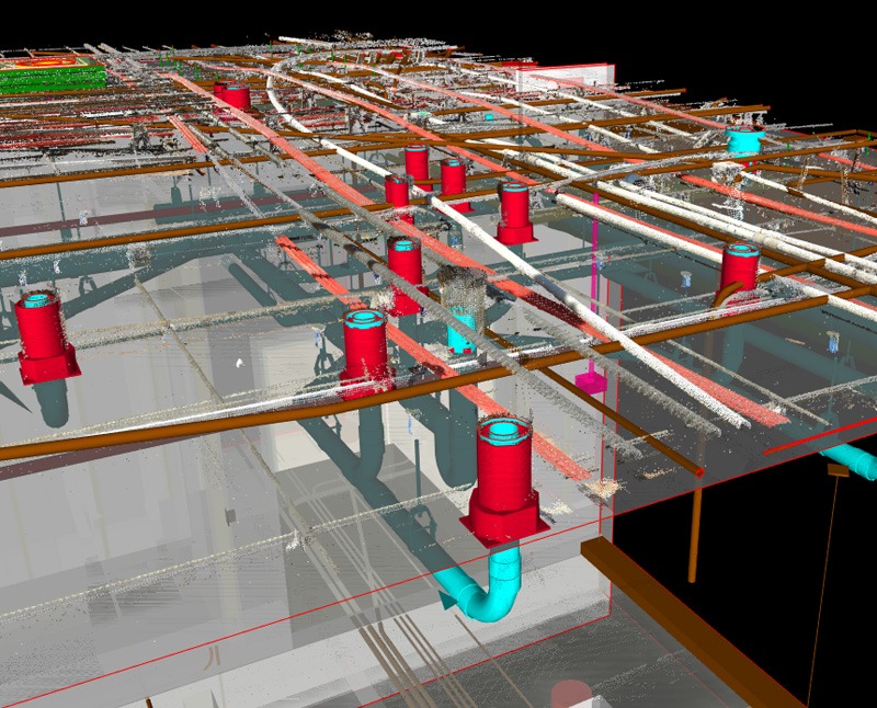
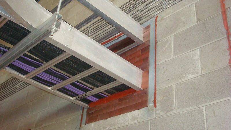
A benefit of specifying pre-formed firestop solutions for each application is that firestopping becomes planned rather than an afterthought. Pre-planned firestopping is far more likely to consistently meet the NBCC requirement of installing firestops “as tested.” This eliminates the need to request and hope for firestop TEs, along with their inherent costs and delays.
Specifiers should periodically review available pre-formed firestop technologies and update specifications accordingly.
Reducing dependence on technical evaluations and improving TEs
Because many Canadian jurisdictions scrutinize or reject TEs in favour of tested systems, specifications should be written to minimize the need for TEs wherever practical.
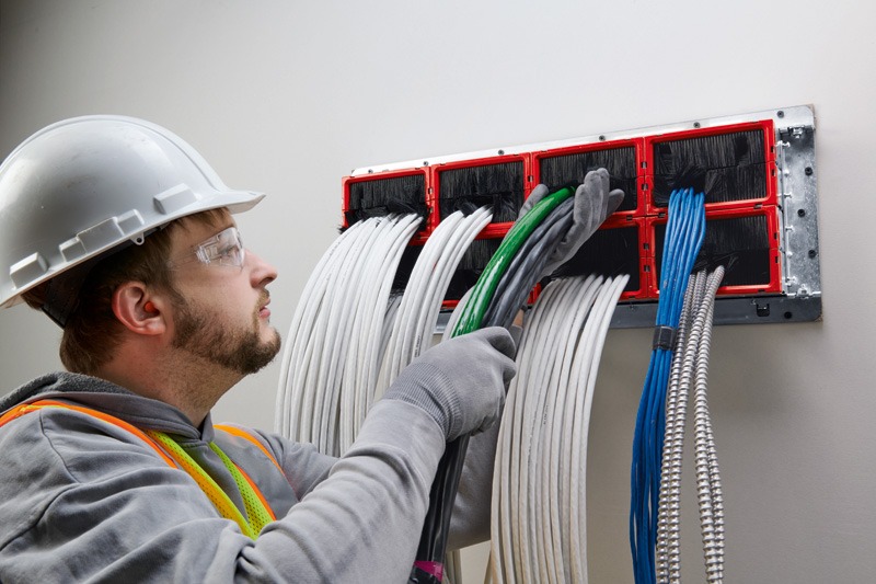
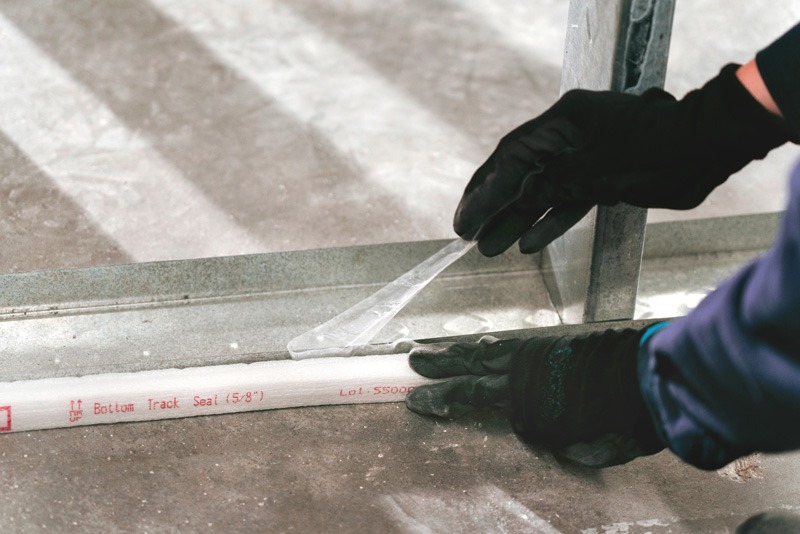
A few jurisdictions will take the time and trouble to evaluate the technical basis of any proposed TE critically, scrutinizing the applicability of the referenced listings and tests on which the TE is based, as listed in the document. Sometimes the TE is rejected based on the jurisdiction’s technical opinion. Such rejections may, in fact, be warranted based on how much of a “stretch” the TE is from tested systems. Some firestop manufacturers have only a few listings (fire tests) to draw from, some have dozens, some have hundreds, and a few even have thousands. It is clear that questionable “stretches” will be attempted, depending on whether the given firestop manufacturer actually has fire tests that are sufficiently close.
To improve the quality and credibility of TEs, UL Solutions created the Technical Evaluation Developer Program. Participating manufacturers must demonstrate personnel competency, implement quality-management procedures, undergo audits, and submit evaluation concepts for periodic validation. Accredited participants are identified in UL Product iQ under category WYGB.
Conclusion
Despite the evolution of firestopping technology and practices, many specifications continue to rely on language developed in years past. As a result, specifications often:
- Reference outdated products
- Omit newer tested systems
- Fail to take advantage of labour-saving firestop technologies
- Overlook simplified installation methods
Specifications should be reviewed regularly to reflect the current code edition, testing standards, and available system solutions.
In an industry where thousands of tested systems already exist, many project challenges arise not because compliant solutions are unavailable, but because specifications fail to direct project teams toward those solutions.
Ultimately, the goal is not simply better specifications, but also better buildings that perform as intended, satisfy code requirements, and provide the level of life safety expected by Canadians who live, work, and gather within them.
In the world of passive fire protection, a few pages of better specification language can make all the difference.
Author

John Valiulis is the director of codes and standards with Hilti North America. He has more than 40 years of experience working in multiple countries as a fire protection engineer in research, construction applications, and national codes and standards development. He holds degrees in chemical engineering and fire protection engineering. He has instructed fire protection engineering seminars in North America, South America, Europe, Asia, the Middle East, and the Caribbean and has written for many U.S. and Canadian publications. He has served on six National Fire Protection Association (NFPA) technical committees and numerous ASTM committees. He has contributed to the development of the National Building Code of Canada (NBCC) and the International Building Code (IBC). Valiulis can be reached at john.valiulis@hilti.com.
Sign up for our weekly newsletter
Construction Canada weekly newsletters give the latest AEC industry news for those who build, design, engineer, specify, renovate or operate in the built environment.
Products & Services

Read the Latest Issue
Demo-Casts