Load path oversights: A leading cause of residential structural issues
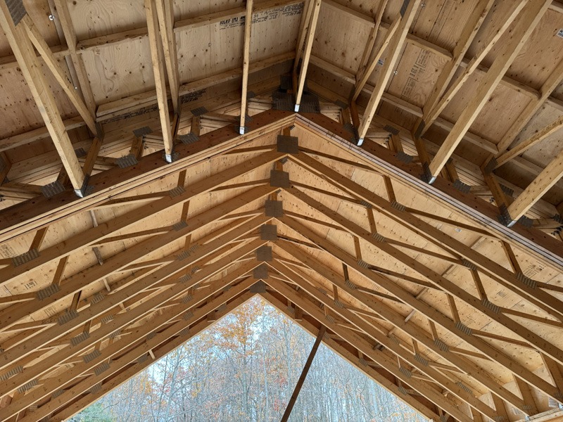
In houses and other small-scale residential construction, performance problems are rarely caused by a single member being “too weak.” More often, the root cause is an interrupted or misunderstood load path, especially at transitions between framing elements, connections, and foundations.
These discontinuities can be small, but the consequences can be large: excessive deflection, floor vibration, drywall cracking, doors that bind, and, in some cases, localized structural distress that is expensive to correct once finishes are installed.
Although wood framing is the primary focus, the load-path principles discussed also apply where steel beams and posts, concrete foundations, or masonry elements form part of the residential structural system.
In Canada, the issue is amplified by the realities of housing stock and climate.
Renovations are common, basements and walkout conditions create frequent vertical discontinuities, and seasonal effects, such as frost and moisture cycling, can magnify serviceability problems over time. This article explains common residential load path oversights and outlines practical measures to reduce risk, with references to Canadian codes and standards where appropriate.
Load paths are often implied, not explicitly traced
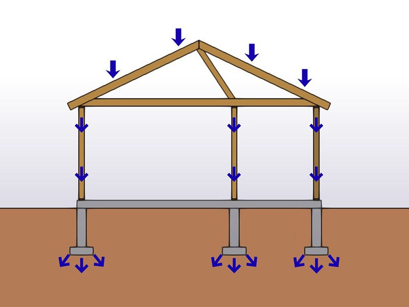
A load path describes how forces move through a structure, from where loads are applied to where the supporting soil resists them. In engineered design, this is typically verified through analysis and detailing. However, in residential work, load paths are often assumed. Drawings show beams, posts, and walls, but the continuity of force transfer among them is not always verified when architectural layouts evolve, construction tolerances accumulate, or renovation scopes change midstream.
Canadian building codes focus on safety and minimum performance, and the National Building Code of Canada (NBCC), adopted with provincial modifications such as the Ontario Building Code (OBC), relies on a combination of prescriptive provisions commonly used for many housing elements and engineered design where conditions fall outside those prescriptive limits. Regardless of the route, the structure still needs an intentional, continuous load path.
Load path oversights tend to fall into three categories: vertical load discontinuities, lateral load discontinuities, and connection and bearing assumptions. Many residential symptoms that appear “mysterious” are explained by one of these categories.
In renovation work, lateral load paths are frequently overlooked when interior walls are removed. Walls that appear non-structural for gravity may function as internal shear walls or braced wall panels required by the NBCC or provincial building codes, such as the OBC. Installing a beam may resolve gravity demands, but it does not replace the lateral resistance provided by these elements.
Vertical load discontinuities across floors
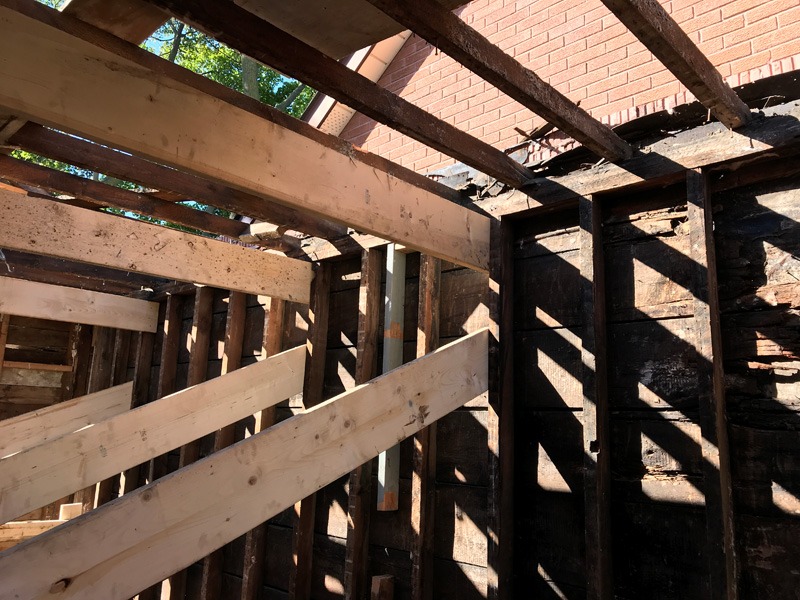
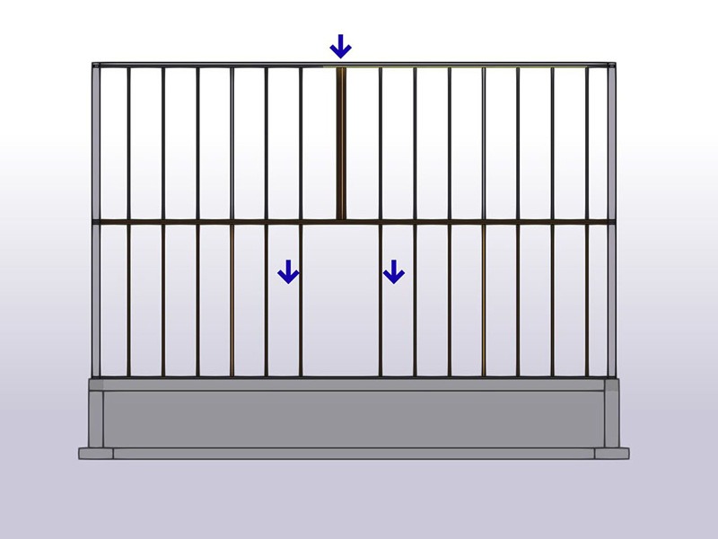
Misalignment of vertical load-resisting elements is one of the most frequent issues observed in houses and small buildings. The load is present, and the members are often conservatively sized, but the force does not have a clear path through successive storeys.
Common situations include:
- Concentrated loads that do not align with supporting framing below, for example, a post supporting a new beam that does not align with a joist, beam, bearing wall, or other designed support below.
- Stud packs or posts terminating on headers that were not designed as transfer members, especially at open-concept layouts where existing openings are widened.
- New point loads introduced during renovations, such as a relocated column or an added steel beam, without reassessing the lower levels and existing foundations.
In these cases, the floor system becomes an unintended transfer structure. It can work in the short term due to redundancy and stiffness distribution, but often, there are serviceability issues. Even when strength is adequate, the stiffness and load sharing may not be.
Transfer through floor framing
Residential floors can redistribute load through joists, blocking, subfloor diaphragms, and adjacent bearing walls. This is often cited informally as evidence that a misalignment “doesn’t matter.” The problem is that the redistribution path is rarely quantified or detailed. Unintended transfer can introduce:
- Local crushing at bearing points (wood perpendicular-to-grain, concrete edge bearing, or masonry pockets).
- Excess rotation at supports, increasing deflection and crack risk.
- Load concentrations in a small fastener group. For example, joist hangers or ledger connections that were not selected for a concentrated reaction.
When a transfer is required, it should be explicit. This may include a designed header, a beam under a bearing wall, a stud pack sized for concentrated reaction, or a transfer element designed in accordance with relevant Canadian standards, such as CSA O86, Engineering Design in Wood, CSA S16, Design of Steel Structures, and CSA A23.3, Design of Concrete Structures.
Connections govern load transfer
Connections are where load paths become real. A beam can be sized correctly on paper, but if the reaction cannot be transferred through bearing, fasteners, and supporting elements, the system performance suffers. In residential work, connections are sometimes treated as secondary details, especially when construction is fast-paced, and trades rely on habits or generic hardware.
Common connection and bearing oversights seen on site include:
- Relying on bearing alone without positive mechanical attachment, where uplift or lateral movement is possible, such as at roof-to-wall interfaces.
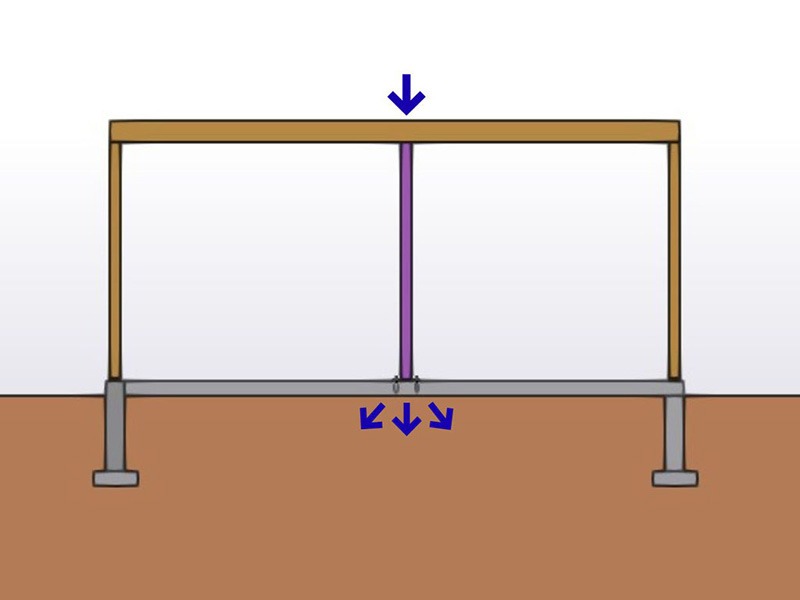
- Underestimating eccentricity at beam supports. For example, when a beam bears on a narrow post cap that shifts the reaction off-centre, it increases rotation and localized crushing.
- Assuming fastener groups share load evenly.
In reality, screw, bolt, and nail groups distribute load based on stiffness, edge distances, and installation quality, and the weakest “fasteners” can demand more attention than expected.
Renovation details that frequently break the load path
Renovations are a high-risk context for load path discontinuities because the original structure was not designed with the new load distribution in mind. Several repeat scenarios appear in forensic investigations and site reviews:
- Partial wall removals where short wall segments remain as “posts,” but there is no continuous stud pack down to a suitable bearing point.
- In many Canadian renovations, the post itself has adequate compressive capacity, but crushing of the top or bottom wall plates perpendicular to the grain governs because the effective bearing area was not verified.
- Large openings created in load-bearing walls where new beam reactions land on the floor framing instead of a designed post-to-foundation line.
- New stair openings that cut joists and remove bridging, reducing floor stiffness and changing the load path for adjacent bearing lines.
- Additions or dormers that impose new roof loads on existing walls and foundations, sometimes in older homes with irregular framing layouts.
These examples all show why field verification matters. Older homes may include balloon framing, non-standard joist spacing, notched members, or previous unpermitted alterations. A simple site opening can reveal whether a presumed stud pack is continuous, whether a beam pocket has adequate bearing length, or whether a supporting wall is aligned with foundation support below.
Completing the load path to the foundation
A complete load path does not stop at framing. Forces must continue through the foundation system and into the supporting soil. Many residential problems originate at or below grade. In Canada, the effects of frost and moisture can worsen small design or construction errors over time. Frequent foundation-level oversights include:
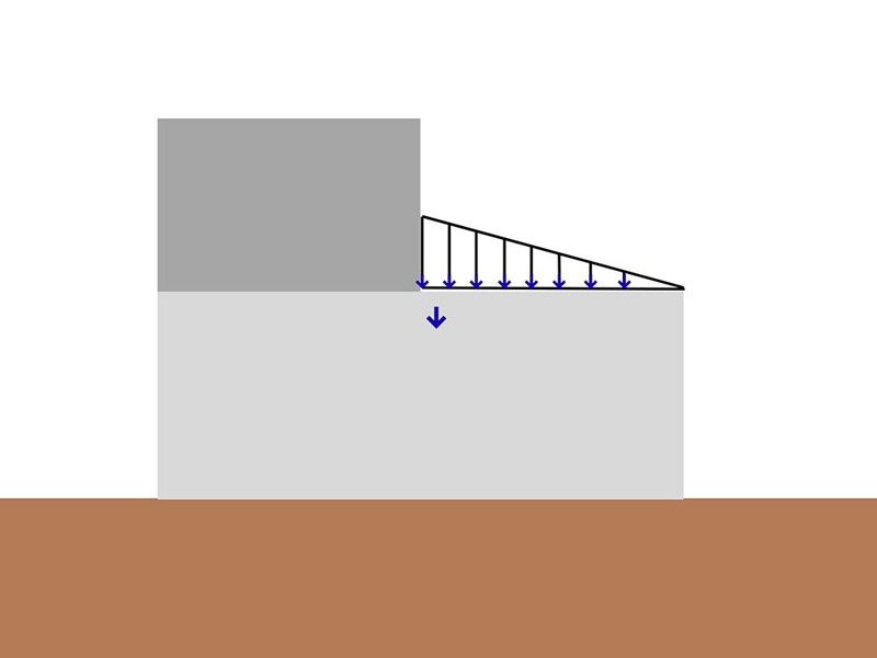
- Concentrated loads introduced onto slabs-on-grade that were intended as non-structural floors. A slab can support localized loads in some cases, but this should be engineered, with attention to thickness, reinforcement, subbase support, and settlement risk; where a full footing is not provided, a locally thickened slab is typically the standard engineered solution.
- Footings sized for uniform wall loads having to support a new point load from a post introduced during a renovation.
- Assuming existing foundations can accept increased load without checking bearing capacity, differential settlement, and the effect on adjacent elements, such as brittle masonry veneer.
Canadian site conditions to explicitly consider
Several site realities commonly influence residential load path performance in Canada.
They include:
- Frost action and seasonal moisture cycling, which can affect shallow exterior footings, porch slabs, garage slabs, and unsupported exterior steps.
- Expansive or sensitive clays in parts of southern Ontario and other regions, which can contribute to heave or settlement, especially when drainage patterns change during renovations.
- High snow loads in many areas of Canada, which increase roof reactions. Unbalanced snow loading from drifting on modified rooflines, such as dormers or stepped additions, can also introduce increased and non-uniform loading that the original load path was not designed
to accommodate. - High wind exposure in coastal and other wind-prone regions, which can increase uplift and lateral demands on roof-to-wall and wall-to-foundation connections and make continuity of the lateral load path particularly important.
- Seismic demands in regions of higher seismicity, particularly parts of British Columbia, eastern Ontario, and southern Quebec, where continuity of lateral load paths, diaphragm connections, and anchorage to foundations requires particular attention.
- Basements and walkouts, which create frequent transitions in foundation height and can introduce discontinuities in shear walls and bearing lines.
The practical implication is that load path checks should be coupled with water management checks. Downspouts, grading, foundation drains, and roof drainage are not simply architectural elements. They influence soil support and, ultimately, the final link in the load path.
Behavioural checks beyond span tables
Span tables and prescriptive rules are useful tools, but they do not replace an understanding of structural behaviour. Many load path errors become obvious when the designer asks a few behavioural questions early in the process:
- Where do the reactions go, and what element receives them?
- Is the supporting element stiff enough relative to what it supports, or will differential stiffness cause localized cracking and movement?
- Do connections and bearing details match the assumed behaviour (pinned, fixed, uplift restraint, and/or lateral restraint)?
- If an element is removed or modified, what is the alternate path, and is it intentional?
For example, a new steel beam replacing a wall can solve a gravity problem, but create serviceability and detailing issues if the end reactions are not aligned with bearing points below. Similarly, a beam pocket cut into a masonry wall may provide bearing, but it can compromise the wall locally if the pocket removes too much material or introduces a moisture pathway.
Practical measures to reduce load path errors
Many residential load path issues can be avoided by applying a consistent, repeatable approach. The following measures are practical for consultants, designers, and builders.
Trace loads deliberately from the roof to the foundation
At the concept stage, sketch the gravity load path with the same discipline used for lateral systems. Identify where major reactions occur and confirm there is a continuous line of support to the foundation. Where transfer is needed, design it explicitly rather than relying on “distribution.”
Verify alignment across floors and document transfer elements
Where posts or stud packs do not align, note the transfer method on drawings. Provide details for headers, beams, blocking, and joist reinforcement where concentrated loads are introduced. If a bearing wall is intended to take a load, confirm it is continuous, not interrupted by openings or non-structural partitions.
Treat connections as primary structural components
Select and detail connectors based on realistic demand, including uplift, eccentricity, and lateral restraint where applicable. For example, provide clear installation notes, specifying fastener type, quantity, and minimum edge distances. Consider construction tolerance: a connection that only works at “perfect” alignment may not perform in the field. Where helpful, manufacturer installation guides for common connectors and fasteners may be referenced for installation practices, but they do not replace engineering design.
Confirm field conditions before relying on existing framing
For renovations, verify as-built framing and supports. Where access is limited, plan selective openings. Confirm member sizes, spacing, bearing conditions, and any signs of prior distress. This step often prevents incorrect assumptions that lead to redesign or costly change orders.
Use serviceability as a diagnostic tool
In many residential cases, early indicators are serviceability-related, such as deflection, vibration, and finish cracking. These symptoms can indicate load-path discontinuities, unintended transfer, or connection slip. Addressing the load path early can reduce rework, protect finishes, and improve long-term performance, thereby supporting sustainability objectives by reducing material waste and the need for repeat construction activities.
Illustrative detailing examples
The following examples are common in residential work and illustrate how small detailing choices affect load path continuity. They are presented generically, and the final design should reflect project-specific loads, materials, and applicable code requirements.
Beam reaction onto a post, bearing, and eccentricity
A built-up wood or steel beam often bears on posts at its ends. If the post cap or bearing plate does not align with the beam centreline, the reaction is eccentric, increasing rotation and local crushing. Practical mitigation includes:
- Use of a centred bearing plate sized to distribute stress within allowable limits.
- Provision of mechanical attachment where uplift can occur, such as wind-governing roof edges.
- Ensuring the post is continuous to a footing designed for the concentrated load.
Point loads on floor systems when a transfer member is needed
When a point load lands between joists, the floor system must transfer the concentrated load to the supporting system. Where this cannot be avoided, typical solutions include double joists, engineered blocking, a short flush or dropped beam to collect load, or aligning the point load to a supporting wall or beam below. The key is to detail the load collection and clearly identify the transfer member on drawings.
New openings, headers, and the ‘short post’ problem
Enlarged openings commonly create short wall segments that are treated as posts. If these segments lack a continuous load path to the foundation bearing, the load can be transferred into the floor structure. Designers should verify:
- Adequate header sizing for combined gravity and lateral effects, where applicable.
- Continuous studs or stud packs to a supporting element below.
- Adequate bearing length and crushing checks, particularly for wood perpendicular to the grain.
Conclusion
Residential structures are often forgiving, but they still rely on continuous, intentional load paths. Small oversights rarely cause immediate failure, but they commonly lead to serviceability issues, long-term performance concerns, and expensive corrective work after finishes are installed.
A practical load-path mindset, tracing forces from roof to soil, detailing transfers where alignment is not possible, and treating connections as core structural components can significantly improve performance without increasing material quantities. In a market where renovations and upgrades are constant, these measures help protect owners, reduce rework, and support more durable, sustainable housing outcomes.
References and suggested Canadian sources
- National Building Code of Canada (NBCC), current adopted edition in the project jurisdiction.
- Ontario Building Code (OBC) or the applicable provincial or territorial building code for the project location.
- CSA O86, Engineering Design in Wood
- CSA S16, Design of Steel Structures
- CSA A23.3, Design of Concrete Structures
- CSA A370 series, Connectors for Masonry (where bearing on masonry or anchorage is relevant).
- Manufacturer installation guides for generic connectors and fasteners (used as installation references, not as proprietary design justification).
Author

Reza Parsiavash, Ph.D., P.Eng., is a licensed structural engineer based in Toronto with more than 20 years of professional experience. He is the founder and principal engineer of Sepco Consulting Engineers. He specializes in the design and assessment of residential, light-commercial, and industrial structures, including structural connection design and evaluation. His work focuses on load path continuity, renovation and retrofit design, and constructible structural design solutions.
Sign up for our weekly newsletter
Construction Canada weekly newsletters give the latest AEC industry news for those who build, design, engineer, specify, renovate or operate in the built environment.
Products & Services

Read the Latest Issue
Demo-Casts