Key considerations when field testing fenestration systems

When installing storefronts, curtain walls, and sloped glazing systems, it is beneficial to test the systems’ air infiltration and water penetration resistance performance at regular intervals, as it can help detect manufacturing, installation, and/or perimeter sealing problems before a substantial portion of the project is completed. If the tests are performed early enough, necessary corrections can be made with less financial impact and limit other deleterious effects on the project. It is advisable to test products at intervals of five per cent, 50 per cent, and 90 per cent completion of the installation on large projects.
A document from the Fenestration & Glazing Alliance (FGIA) called AAMA 503, Voluntary Specification for Field Testing of Newly Installed Storefronts, Curtain Walls and Sloped Glazing Systems, establishes the requirements to evaluate the air infiltration resistance and/or water penetration resistance performances of newly installed storefronts, curtain walls, sloped glazing systems, and their installation during initial construction. This test should be conducted before building occupancy permit is issued, and no later than six months after. AAMA 511, Voluntary Guideline for Forensic Water Penetration Testing of Fenestration Products, must be used if field testing is required more than six months after the building occupancy permit has been issued.

Standard scope
As mentioned, AAMA 503 establishes the requirements for test specimens, apparatus, sampling, test procedures, and test reports to be used in evaluating the performance of newly installed storefronts, curtain walls, and sloped glazing systems as well as their installation during construction. It provides a structured, controllable, and reproducible method for testing.
AAMA 503 recommends including in the project specifications an exact description of the area(s) to be tested. Failure to do so can increase the cost of field testing. Here’s a sample specification that specifiers can use.
- The newly installed (Insert storefront, curtain wall and/or sloped glazing system) shall be field tested, as contractually agreed upon by the interested parties, by an AAMA-accredited independent laboratory, as engaged by (________________), in accordance with AAMA 503, Voluntary Specification for Field Testing of Newly Installed Storefronts, Curtain Walls and Sloped Glazing Systems.
- The area(s) to be tested is (are) as follows: (Insert an exact description of the area(s) to be tested)
- Air leakage resistance tests shall be conducted at a uniform static test pressure of _____Pa (____ psf). The maximum allowable rate of air leakage shall not exceed ____ L/s•m2 (____ cfm/sf).
- Water penetration tests shall be conducted at a static test pressure of _____ Pa (____ psf).
Specification considerations
Per AAMA 503, the test specimen(s) should be determined after carefully considering the project size. It is not cost effective to test large area(s) on a small project (less than 93 m2 [1,000 sf] of glazing). A glazing specimen of 9.3 m2 (100 sf) may provide the required information. On all projects, regardless of size, the specifier should also determine how many specimens and/or their desired surface area are required to establish a reasonable measure of quality for the entire project. ASTM E122, Standard Practice for Calculating Sample Size to Estimate, With Specified Precision, the Average for a Characteristic of a Lot or Process, provides more information on determining the number of test specimens.
Further, the specifier should balance the cost of the specimen or specimen preparation, as well as the cost of testing and restoration of surrounding components and finishes to their original condition, before determining the number, location, and size (surface area) of test specimens. On larger projects, a formal cost-benefit analysis is appropriate. On smaller projects, the specifier should ensure that the cost of testing and building restoration is less than the cost of the glazing system(s).
Field air leakage resistance tests are only recommended for discrete ‘punched opening’ curtain walls, storefronts, and sloped glazing elevations. It is not recommended for a portion of a continuous system due to the problems associated with compartmentalization and identification of extraneous air leakage (tare).
The specified static water test pressure differential should not exceed two-thirds of the tested or rated laboratory performance. If any test specimen fails to meet the requirements, refer to Section 7.3.7 of AAMA 503.
If water penetration testing reveals leakage that cannot be solely attributed to the glazing system, forensic testing must be initiated by using AAMA 511 and ASTM E2128, Standard Guide for Evaluating Water Leakage of Building Walls.
The project specifications and/or the contract documents must clearly identify the responsible party who is liable for the costs associated with the initial field testing, retesting and, if necessary, forensic testing.
Testing must be performed by an AAMA-accredited laboratory or field-testing agency. This assures the specifier the agency has the staff, training, experience, and calibrated equipment to properly perform field testing.
Test methods
AAMA 503 recommends testing resistance to air infiltration using static air pressure difference, as described in ASTM E783, Standard Test Method for Field Measurement of Air Leakage through Installed Exterior Windows and Doors, and testing resistance to water penetration using static air pressure difference, according to ASTM E1105, Standard Test Method for Field Determination of Water Penetration of Installed Exterior Windows, Skylights, Doors, and Curtain Walls, by Uniform or Cyclic Static Air Pressure Difference.
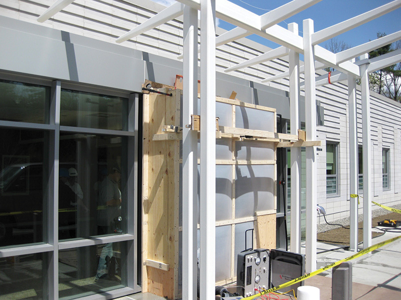
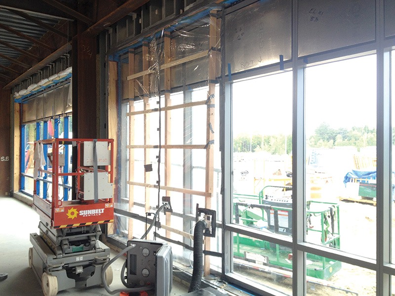
Test chamber arrangement
The test chamber must be applied to the interior or exterior of the wall, curb, or roof construction to create a pressure differential across the specimen assembly, including perimeter frame intersections and perimeter seals, subframes, receptors, and flashing.
Joints between the specimen and the adjacent wall, curb, or roof can be included in the test specimen unless otherwise noted in project specifications. However, it is not practical to install a chamber on a segment of a continuous horizontal or vertical member. Therefore, air leakage testing of these systems is not recommended.
The test must be performed soon after the specimen is installed, sealants are cured, and before the installation of gypsum wallboard, insulation, or other finish materials. If interior wall materials have been installed, they must be removed to visually check for water leakage.
Wind and other environmental conditions (barometric pressure, rain, and temperature changes) can adversely impact field testing performance. Therefore, the specimen should be isolated from adverse ambient surroundings with a barrier, and conditioned, if necessary, to protect it from environmental settings that may affect test results.
Site preparation
The test specimen must be representative of typical installations and construction for the project. The specimen(s) must have no outstanding punch list items, visible damages or irregularities, and not be singled out due to obvious performance problems.
A single 9.3-m2 (100-sf) test specimen is typically recommended when contained within a larger wall area. This recommendation does not apply to punched openings less than 9.3-m2 (100-sf).
The specimen must include perimeter seals, typical splices, frame intersections, and, if applicable, at least two entire vision lites and two spandrel lites containing an intermediate vertical and an intermediate horizontal.
If the specimen contains an integral ventilating system/device, it must be tested twice for both water penetration resistance and air leakage resistance: once with the venting portion of the ventilating system/device in the closed position and again, if necessary, with the venting portion closed and taped or sealed.
After the specimen(s) locations have been selected and the chamber is prepared for testing, it is important to conduct a pretest inspection to check:
- plumb, level, and square of the specimen
- operation of the specimen (if applicable)
- pre-test condition of all surfaces to confirm they were in a condition where a judgment can be made as to whether water penetration is a result of this testing
Whenever possible, the specifier must define the field-testing requirements in the project specifications, including the number of tests and their location. This will provide some assurance that consideration has been given to the complexity of field testing prior to bidding and communicate the requirements to those who will be responsible for or involved in it.

Test procedures
Air leakage and/or water penetration resistance tests must be performed at pressures specified in Sections 7.2.3-7.3.1 of AAMA 503.
If both tests are to be conducted in sequence, the air leakage resistance test must be conducted before the water penetration resistance test.
If there is reason to believe that residual water from rain or other sources could be in the specimen, a negative (outward) pressure test followed by a positive (inward) pressure test must be conducted at the same pressure differential used for the performance test to purge the specimen of any residual water. The specimen gaskets or weatherstrips must be examined and dried before proceeding with the air leakage resistance test.
Air leakage rate
An air leakage resistance test must be conducted at a minimum uniform static test pressure of 75 Pa (1.6 psf) or as specified for the project. However, this must not exceed 300 Pa (6.2 psf). Air leakage resistance (when required) shall be determined and adjusted to standard conditions per ASTM E783.
If changes in outdoor wind speed and/or indoor air pressure cause static air pressure difference readings to fluctuate more than ± 10 per cent from the specified test pressure, one of the following methods must be used:
- Method A: The specimen and/or test chamber must be shielded or temporarily enclosed to minimize these fluctuations.
- Method B: Record 10 readings of airflow, evenly distributed over a 30-minute period for each of the total and extraneous air leakage (tare) measurements. Report both the average of the 10 readings and standard deviation in the test report.
- Method C: Equipment used to maintain the pressure differential during testing must continuously monitor test pressure and self-adjust to maintain the appropriate test conditions.

Extraneous air test
Measurement of extraneous air leakage (tare) readings require special consideration on many on-site installations. It is recommended to review the installation details to identify sources of tare leakage before testing. Precautions must be taken to minimize tare. If tare exceeds the limits specified in ASTM E783, then the chamber can be attached to the perimeter frame of the test specimen to obtain an accurate tare reading.
The intent of the air leakage test is to measure only exterior air leakage through the joints, fixed glazing, hardware, etc., and within the area enclosed by the specimen frame. The air is assumed to be coming from the exterior of the building directly through the specimen. Other sources of air infiltration (i.e. through fastener holes, interior trim and mullion covers, exterior panning systems, receptors, flashing, and through leakage in the testing equipment or air chamber attachment to the specimen) are referred to as extraneous air leakage and must be accounted for.
Since it is not practical to account for all sources of air leakage when testing a portion of a continuous curtain wall or sloped glazing, it is not recommended to perform field air leakage tests on these systems.
The maximum allowable rates of air leakage for field testing must not exceed 1.5 times the project specification rate, or 0.5 L/s•m2
(0.09 cfm/sf), whichever is greater. The specifier may require project-specific air leakage, but this must be stipulated in the project specifications.
The purpose of in-field air leakage testing is to provide reasonable assurances the fenestration product will perform to its specified or rated level with allowances for field reductions, primarily related to ambient environmental conditions and installation.
As expected, field installation conditions will influence product performance. Products tested in the laboratory are perfectly plumb, level, and square in a precision opening. Field test specimens, although installed within acceptable industry tolerances, are rarely perfectly plumb, level, and square. Shipping, handling, acts of subsequent trades, ageing, and other environmental conditions will impact the performance of the installed specimen. A 50 per cent increase in the allowable air leakage for field testing is specified as a reasonable adjustment for the differences between a laboratory test environment and a field test environment.
Water penetration resistance
Water penetration resistance performance shall be determined per ASTM E1105 using Procedure A, “Uniform Static Air Pressure Difference.” The field water penetration resistance tests shall be conducted at a static test pressure of two-thirds of the specified project water penetration test pressure, but not less than 200 Pa (4.18 psf). The specifier may increase the field water test pressure to the value specified for the project, but this should be stipulated in the project specifications.
If the project does not have a specified water penetration resistance test pressure, the value should be equal to the manufacturer’s published laboratory test pressure or 20 per cent of the positive allowable stress design (ASD) wind load, whichever is greater, times 0.667.
The default pressures used for onsite water penetration resistance tests are not the same as the laboratory test pressure to accommodate for ambient environmental conditions and installation. Therefore, a 1/3 reduction of the test pressure for field testing is specified as a reasonable adjustment for the differences between a laboratory test environment and a field test environment.
With all operable portions of the specimen closed and locked, the specimen will be subjected to a water penetration test in accordance with ASTM E 1105 with continuous pressure and water application. One must observe and note all points of water penetration, if any, occurring during the test. If the origin of the water leakage cannot be definitively determined, a forensic evaluation must be performed using the procedures outlined in AAMA 511, while maintaining the test pressures defined in AAMA 503.
Unless expressed otherwise in project specifications, water penetration shall be defined as:
- a) Water penetration attributable to the surrounding wall conditions—The presence of water not contained within drained flashing, gutters, and sills, which did not originate from the fenestration product or the joint between the fenestration product specimen and the wall/roof.
- b) Water penetration attributable to the fenestration product specimen—Per ASTM E1105 with the modification that the collection of up to 15 ml (0.5 oz) of water on an interior horizontal framing member surface in the 15-minute test period will not be deemed a failure.
- c) Water penetration attributable to the perimeter joint—Water not controlled by a water management system that indisputably originates at the perimeter joint.
If leakage through frames, frame corners, exterior perimeter seals, or adjacent materials is not visible from the interior and leakage appears on the floor below the test specimen, the lower floor should be inspected for signs of leakage. A means to view, observe, or identify test-related water penetration beyond the planes of water penetration should be accommodated, if desired by any responsible party, provided the appropriate parties know repairs must be made.
If any of the specimen(s) do not conform to the prescribed air leakage or water penetration resistance requirements, or both, the manufacturer and/or the installer must have the opportunity to perform a site inspection and determine the reason for noncompliance. Noncompliant specimen(s) must be repaired as required and retested as soon as practical. The remedial work must be recorded and approved by the specifying authority, architect, and/or owner. Upon satisfactorily passing a retest, the remedial work performed should be considered for similar conditions on the remainder of the project.
If problems with a specimen installation are observed, they shall be brought to the attention of the responsible contractor and/or manufacturer representative.
The observations to be recorded must include, but not be limited, to:
- Deterioration of building elements due to water penetration
- Deviations of the installation from the drawings of record
- Staining or discolouration of building components
- Evidence of damage to either the installed product or the surrounding building elements
- Unusual or unexpected evidence of water penetration or air leakage requiring remediation
- Any observed performance or installation details that might be deemed of importance to a subsequent forensic investigation
AAMA 503 also provides guidance on calibration of all measuring apparatuses as well as validation of equipment used for onsite testing. Detailed guidelines on the data to be included in test reports are also provided in the standard. This way, AAMA 503 provides a detailed framework for ensuring newly installed storefronts, curtain walls, and sloped glazing systems perform as they are intended to, thereby preventing costly remedial work.
References
- AAMA 503-24, Voluntary Specification for Field Testing of Newly Installed Storefronts, Curtain Walls and Sloped Glazing Systems.
- AAMA 511-22, Voluntary Guide for the Forensic Evaluation of Water Intrusion at Fenestration Products.
- ASTM E122-117(2022), Standard Practice for Calculating Sample Size to Estimate, With Specified Precision, the Average for a Characteristic of a Lot or Process.
- ASTM E2128-20, Standard Guide for Evaluating Water Leakage of Building Walls.
- ASTM E783-02(2018), Standard Test Method for Field Measurement of Air Leakage Through Installed Exterior Windows and Doors.
- ASTM E1105-15(2023), Standard Test Method for Field Determination of Water Penetration of Installed Exterior Windows, Skylights, Doors, and Curtain Walls, by Uniform or Cyclic Static Air Pressure Difference.

Amy Roberts is the Canadian code and advocacy director for the Fenestration and Glazing Industry Alliance (FGIA). She leads FGIA’s Canadian codes and regulatory initiatives with a focus on building and energy codes, standards development, and industry advocacy. In her role, she also supports the FGIA FENBC Region, working closely with stakeholders to represent industry interests at both regional and national levels. With more than 25 years of experience in glass and insulating glass (IG) manufacturing, as well as residential and commercial window production, Roberts brings deep technical expertise and strategic insight to advancing the Canadian fenestration and glazing industry. She can be reached at aroberts@fgiaonline.org.
Sign up for our weekly newsletter
Construction Canada weekly newsletters give the latest AEC industry news for those who build, design, engineer, specify, renovate or operate in the built environment.
Products & Services


Read the Latest Issue