Key updates in CSA A23.3-24 Annex D: Advancements in concrete anchorage design and installation

The Canadian Standards Association (CSA Group) CSA A23.3 standard governs the design of concrete buildings in Canada. It is referenced by both the National Building Code (NBC) and provincial or territorial building codes. NBC 2020 refers to the 2019 edition of CSA A23.3 (CSA A23.3-19) for designing concrete structures. Annex D of CSA A23.3 is dedicated to the design, installation, and quality assurance requirements for cast-in and post-installed mechanical and adhesive anchors in concrete. This annex became normative (i.e. mandatory) in the 2019 edition of CSA A23.3, whereas it was informative (non-mandatory) in the 2014 edition. As a result, the requirements outlined in Annex D (2019) are now enforceable under NBC 2020 and any provincial or territorial codes that have adopted CSA A23.3-19.
The latest version of CSA A23.3 was published in June 2024 and includes several updates to Annex D to further refine and enhance anchorage design requirements. Given that CSA A23.3-19 was referenced by NBC 2020, it is expected that CSA A23.3-24 will be referenced by NBC 2025 once adopted. The revisions in the 2024 edition build upon the foundation set in CSA A23.3-19 by incorporating new research, improving design consistency with international standards, and addressing identified challenges in anchorage design. These changes ensure Canadian anchorage provisions remain aligned with best practices and evolving industry needs. Additionally, the 2024 version of Annex D serves as a reference design anchor standard for other Canadian design standards, including CSA S16, Design and Construction of Steel Structures, and CSA N287.3-25, Design Requirements for Concrete Containment Structures for Nuclear Power Plants.
This article provides an overview of the major technical and editorial changes introduced in Annex D of CSA A23.3-24. These updates reflect advancements in anchorage design methodologies, improved safety considerations, and a more structured approach to anchor quality assurance and installation procedures. By incorporating the latest research and industry best practices, the revisions aim to align Canadian standards more closely with international codes such as ACI 318. Additionally, the modifications address gaps identified in previous editions, ensuring greater clarity, consistency, and applicability in real-world construction scenarios. These changes impact anchor capacity, expand the scope of Annex D, introduce enhancements to installation and quality assurance requirements, and include minor editorial updates to improve clarity and consistency. Below is a comprehensive list of all major changes introduced in Annex D:
- Inclusion of screw anchors
- Incorporation of post-installed reinforcing
bar systems using development and splice length provisions - Revision of interaction checks for anchors under tension and shear
- Incorporation of an overturning compression factor for breakout strength
- Updates to installation and quality assurance requirements for post-installed anchors and reinforcing bars
- Recalibration of resistance factors (R factors) for consistency with ACI 318
- Inclusion of shear lug design in Annex D
- Editorial updates and clarifications
Each of these changes is explained in detail in this article, along with relevant figures and tables from CSA A23.3-24 to illustrate the updates.
Inclusion of screw anchors
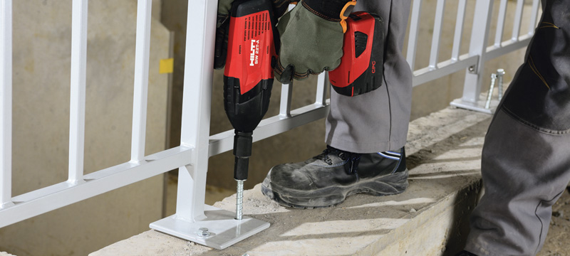
The 2024 edition of Annex D introduces screw anchors as a recognized type of post-installed mechanical anchor. In general, screw anchors as shown in Figure 1 offer a simpler installation process compared to expansion anchors and adhesive anchors. According to CSA A23.3-24, a screw anchor is defined as ‘a post-installed threaded, mechanical anchor inserted into hardened concrete that transfers loads to the concrete by engagement of the hardened threads of the screw with the grooves that cut into the sidewall of a predrilled hole during anchor installation’ (Clause D.2 CSA A23.3-24).
Key updates about this change include:
- Testing requirements for screw anchors are based on ACI 355.2-22, as specified in Clause D.1.3(e) of CSA A23.3-24. ACI 355.2 outlines the testing and evaluation criteria for post-installed mechanical anchors intended for use in concrete. It is important to note that prior to the 2024 edition of CSA A23.3, ACI 355.2 was used exclusively for qualifying expansion and undercut anchors. The 2024 revision extends its application to screw anchors, ensuring consistent performance evaluation across different types of mechanical anchors.
- Design equations in Annex D continue to apply the existing mechanical anchor equations from CSA A23.3-19 for both tension and shear in Clause D.6 and D.7, ensuring consistency across anchor types and simplifying the design process. No new equations were introduced specifically for screw anchors.
- New installation requirements for screw anchors, including a provision in Clause D.1.6 that explicitly states: “The removal and resetting of post-installed mechanical anchors shall not be permitted.” This requirement reinforces proper installation practices and prevents re-use, which could compromise anchor performance and structural integrity.
- Minimum edge distances and spacing requirements for screw anchors are specified in Clause D.9. The minimum centre-to-centre spacing for post-installed screw anchors is the greater of 0.6hef and 6da, as specified in D.9.2(c). The minimum edge distance for screw anchors is 6da, similar to adhesive and undercut anchors, as stated in Clause D.9.4. The critical edge distance for screw anchors is 4hef, similar to expansion anchors, as specified in Clause D.9.7. It should be noted that all minimum spacing, minimum edge distance, and critical edge distance requirements in Clause D.9 apply in the absence of product-specific ACI 355.2 test information.
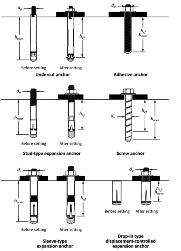
Figure 2 in CSA A23.3-24 is completely re-drawn showing the various types of cast-in and post-installed anchors, including screw anchors.
Post-installed rebar: Development and splice length provisions
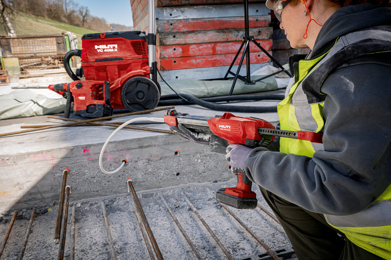
CSA A23.3-24 recognizes post-installed reinforcing bars (PI rebars) using development and splice length provisions as a new addition in both Annex D and Clause 12 (Development and Splices of Reinforcement). This change establishes a standardized qualification and design process to ensure consistent design and testing criteria for PI rebar systems.
Key updates about this change include:
- A new provision in Clause D.1.4 explicitly states: “Where development and splice length provisions in accordance with Clause 12.2 and 12.3 are used for post-installed reinforcing bar systems, those systems shall be qualified in accordance with an applicable standard.”
- Post-installed reinforcing bars can generally be designed using two different approaches:
- Treating them as anchor elements and applying anchorage equations from Annex D to determine capacity.
- Following development and splice length provisions, similar to cast-in reinforcing bars.
- Historically, post-installed reinforcing bars using development and splice length provisions were not explicitly covered in CSA standards. Prior to CSA A23.3-24, some adhesive anchor manufacturers provided evaluation reports referencing the test program outlined in ICC-ES Acceptance Criteria (AC) 308; however, this test program for post-installed rebar systems using development and splice lengths was never required by CSA A23.3. CSA A23.3-24 addresses this gap by defining post-installed reinforcing bars in Clause D.2, establishing their qualification program in Clause D.1.4, and linking them to Clauses 12.2 and 12.3 for development and splice length calculations.
- To establish qualification and evaluation requirements for post-installed reinforcing bar systems, the American Concrete Institute (ACI) published a new standard in November 2024 titled: ACI CODE 355.5-24, Post-Installed Reinforcing Bar Systems in Concrete—Qualification Requirements and Commentary. This document provides a standardized framework for testing and evaluating PI rebars using both organic (polymer) binders and hydraulically activated binders (cements). These tests are designed to directly compare the behaviour of cast-in versus post-installed bars when splitting governs the failure mode. A very stiff adhesive can cause high shear lag, potentially resulting in a zipper-type failure for bars placed near an edge. Conversely, if the bond is too flexible, the post-installed bar may experience relaxation, which could allow excessive joint opening between the existing and new concrete, compromising shear transfer or increasing the risk of reinforcing bar corrosion.
- Since ACI CODE 355.5-24 had not yet been published at the time of CSA A23.3-24 development cycle, it could not be explicitly referenced in Annex D. Instead, the term “applicable standard” was used to allow for future alignment with ACI 355.5 once
officially released. - Additionally, Clause D.1.4 includes a note referencing the Cement Association of Canada’s Concrete Design Handbook, where it is expected that ACI 355.5-24 will be included to provide further guidance on the qualification of post-installed reinforcing bars.
Revised interaction checks for anchors in tension and shear
The 2024 edition of Annex D provides a revised approach to reduce conservatism for anchors subjected to combined tension and shear forces by separating steel and concrete failure modes.
Key updates about this change include:
- Removal of the trilinear interaction equation, which was previously applied to all anchors regardless of their failure modes.
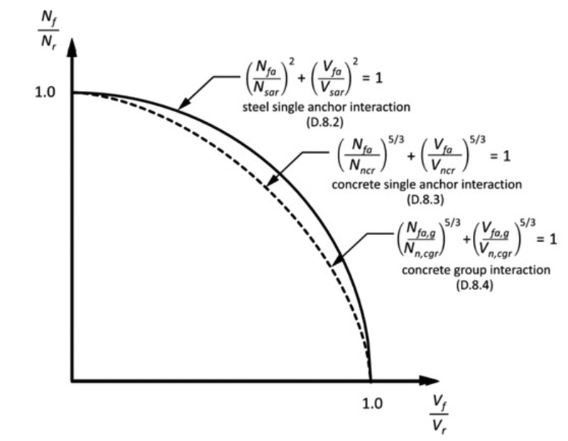
- Introduction of a less conservative interaction check for steel strength of a single anchor or an individual anchor within a group (Clause D.8.2).
- Introduction of a less conservative interaction check for concrete strength of a single anchor (Clause D.8.3) and an anchor group (Clause D.8.4).
- Updates to Table D.1 and Figure 4 with revised interaction checks.
Overturning compression factor for breakout resistance
This change introduces a new factor (ψcm,N) to account for the effects of compressive forces acting on the anchor baseplate in the calculation of breakout resistance for anchors in tension.
Key updates about this change include:
- Ensures the ψcm,N factor is always greater than or equal to 1.0 in the breakout calculation equation, which can either increase breakout resistance or leave it unchanged.
- Reduces the level of conservatism associated with the breakout calculation in tension for cases where the compression field under the baseplate influences the fracture process of the tension-loaded anchors.
Updates to installation and quality assurance requirements
Significant updates were made to the installation and quality assurance requirements in Clause D.10 to enhance clarity and strengthen provisions, ensuring the proper installation of post-installed anchors and reinforcing bars.
Key updates about this change include:
- Includes post-installed reinforcing bars under the installation and quality assurance requirements in Clause D.10.
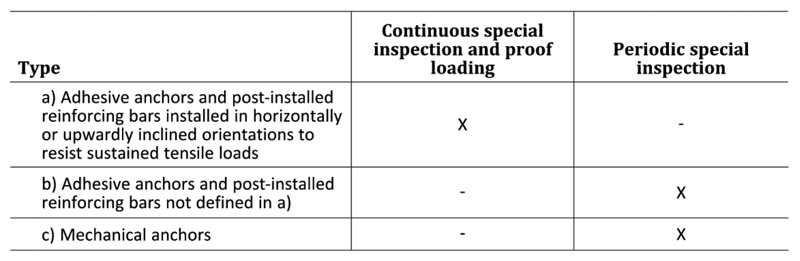
- Specifies the minimum level of inspection requirements for post-installed adhesive and mechanical anchors, as well as post-installed reinforcing bars, including periodic and continuous special inspections, as outlined in Table D.3 (CSA A23.3-24).
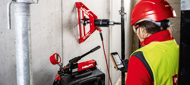
- Introduces new proof load testing requirements, enhancing verification procedures for installed anchor capacity.
For a more detailed discussion on the installation and quality assurance requirements of post-installed anchors and reinforcing bars, including key updates from the 2019 to the 2024 edition of CSA A23.3, refer to the author’s article “Advancing Concrete Anchor Installation Standards,” published in the January 2025 issue of Construction Canada.
Recalibration of resistance modification factors (R factors)
CSA A23.3-24 revises certain resistance modification factors (R factors) in Clause D.5.3 to align with the corresponding factors in ACI 318-14, improving consistency and reliability.
R factors are used to determine anchor resistances in both tension and shear.
R factors are calibrated such that for the equivalent failure mode and condition, R*ϕc and R*ϕs are equivalent to the analogous ϕ factor in ACI 318-14.
The table titled, “R factor revisions in Clause D.5.3” (above) is a summary of R factor revisions in Clause D.5.3, showing only the values that have changed in CSA A23.3-24 compared to CSA A23.3-19.
Inclusion of shear lug design
Shear lugs, as shown in Figure 6, are in common use in concrete structures, particularly where the shear capacities of anchors are insufficient due to steel strength or edge breakout limitations. Shear lug concrete design provisions are now formally included in Annex D (Clause D.11), providing an alternative design methodology for shear load transfer in baseplate connections where anchors alone may be insufficient.

Key updates about this change include:
- Introduction of a new equation (Eq. D.50) for the bearing resistance of shear lugs in shear.
- Incorporation of an implicit interaction between bearing resistance in shear and axial forces through the modification factor ψbrg,sl
(Eq. D.51–D.53). - Reference to the concrete breakout equations for anchors (Eq. D.33) to calculate the concrete breakout resistance of shear lugs.
- Provisions for multiple shear lugs on a common plate.
- The steel design of shear lugs is beyond the scope of Annex D and should be addressed using other applicable standards, such as CSA S16-24.
Editorial updates and clarifications
CSA A23.3-24 includes several editorial refinements to improve clarity, usability, and alignment with other standards. These updates do not change the fundamental design requirements but ensure that the document is more user-friendly and consistent across different clauses.
Key editorial updates include:
- Terminology standardization—Terms such as “anchor bolt” and “anchor rod” have been clarified and standardized to reduce ambiguity in design and installation documents.
- Reorganization of figures—All figures have been relocated closer to the relevant clauses to enhance readability and improve reference efficiency.
- Alignment with NBC 2020 seismic category classification—Clause D.4.3.3 now uses the seismic category (SC) terminology introduced in NBC 2020 to classify the seismic hazard level of a building site. The SC system considers factors such as spectral acceleration and building importance to determine appropriate seismic design requirements. This update enhances consistency between CSA A23.3-24 and NBC 2020’s seismic provisions.
- Correction of variable nomenclature—Some variables and symbols have been revised to maintain consistency with CSA A23.3-24 and align with ACI 318.
- Updated cross-references—Internal cross-references between clauses have been corrected to ensure accurate navigation within the document.
These refinements improve the document’s usability for engineers, contractors, and inspectors, ensuring anchorage design and installation practices remain well-understood and effectively implemented in the field.
Conclusion
The updates in CSA A23.3-24 Annex D represent a meaningful advancement in concrete anchorage design and construction practices across Canada. With clearer guidance, expanded scope, and improved alignment with related standards, these changes support safer, more consistent, and more efficient implementation. The revisions ensure anchorage systems meet the evolving demands of modern construction.
R factor revisions in Clause D.5.3
For an anchor steel strength using a ductile steel element:
| Tension loads | CSA A23.3-19 | CSA A23.3-24 |
| 0.80 | 0.85 |
For an anchor steel strength using a brittle steel element:
| CSA A23.3-19 | CSA A23.3-24 | |
| Tension loads | 0.70 | 0.75 |
| Shear loads | 0.65 | 0.70 |
For an anchor in concrete breakout, side face blowout, pullout,
or pryout strength:
| Condition B* | ||
| CSA A23.3-19 | CSA A23.3-24 | |
| Shear loads | 1.00 | 1.05 |
| Tension loads | ||
| Cast-in headed studs, headed bolts, or hooked bolts |
1.00 | 1.05 |
| Post-installed anchors (category determined in accordance with ACI 355.2 or ACI 355.4) |
||
| Category 3 (high sensitivity to installation and lower reliability) | 0.75 | 0.70 |
*Condition B applies where such supplementary reinforcement is not provided or where pullout or pryout strength governs.
Author
Ali Ahrabi graduated with a bachelor’s degree in civil engineering in 2006 and obtained his master of science in civil engineering from Concordia University in 2012. He has been a professional engineer in the province of Quebec (Ing.) since 2013 and has experience in various engineering settings. Ahrabi currently serves as the manager of codes and approvals at Hilti Canada. He contributes to developing fastening-related provisions within the National Building Code (NBC) and Canadian Standards Association (CSA) with heavy emphasis on anchors, including contributions to CSA technical committees A23.3, S6, S16, and S304. He can be reached at ali.ahrabi@hilti.com.
Sign up for our weekly newsletter
Construction Canada weekly newsletters give the latest AEC industry news for those who build, design, engineer, specify, renovate or operate in the built environment.
Products & Services


Read the Latest Issue