Wind Design For Roofing: Misconceptions and consequences
by Elaina Adams | May 1, 2012 11:05 am
 [1]
[1]By Josh Jensen, AScT, CHI, RRO, RRC
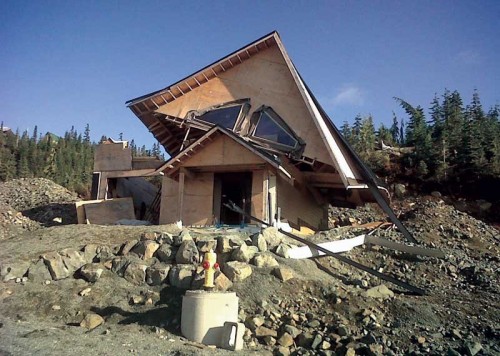
For the last few years, the media has highlighted roofing failures caused by wind. Although these problems sensationalize the effects of global warming, they are not new and have occurred since buildings were first constructed. The major contributing factor to many of these failures is the roof or perimeter flashing was not properly designed to meet the project requirements––such as location and occupancy type.
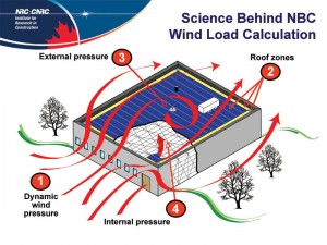
Depending on its direction, wind acts on the building in different ways. As it collides with the structure, it travels up and over, increasing in speed––similar to the effects of an airfoil on a wing. This creates a negative suction wind load on the roof membrane that is not uniform; the result is various areas that have higher wind load (i.e. corners) from lower wind load (i.e. field).
The effects on the flashing are much more dynamic. As the wind travels up the building, it gets behind the flashing and pries it up; at the same time, however, the wind colliding with the flashing exterior is pulling on it from the top. Of course, this only occurs with the ‘perfect’ building––a box with a square roof located in a field. It gets more dynamic when there are interesting building shapes, locations, and configurations.
One often hears about catastrophic failures where the entire roof system becomes detached from the building and ends up in the parking lot or on the neighbouring facility, but failures can also be small where a fastener pulls through a roof membrane or blows off. Unfortunately, wind-related damage due to improper design happens more frequently than most people think. Often, an owner calls a contractor to come repair the damage, but does not dwell on it too much.
 [2]
[2]Photos courtesy JRS Engineering
The cause
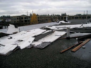
This author has observed many roof failures that, despite being attributed to wind forces, were a result of contractor error. However, if one looks at a specific group of projects with a roof design segment, most consequent failures are as a result of poor design. While improper design pressures are occasionally used, the majority occurs where design pressures and roof assembly are correct, but the various flashings and accessories are not.
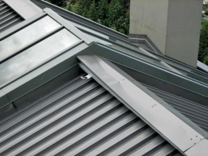
The vast majority of catastrophic failures due to wind effects are a result of improper flashing design at the roof’s perimeter. The perimeter flashing, which is most commonly considered moisture protection, is also a significant part of the wind attachment system for the roof assembly. When properly installed, flashing acts like a large termination bar holding the membrane in place. Wind comes up the side of the building and gets under the flashings and membrane at the perimeter. If the flashing is not properly secured and becomes dislodged from the edge of the building, the rest of the roof is exposed and the roof starts to ‘peel’ off the underlying substrate.
 [3]
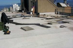
[3]Where do designers go to get the proper information to design the roof system to ensure the roofs do not fail? Most specifications provide a reference to a Factory Mutual (FM) Global requirement, such as a FM 1-60 rating. However, FM Global is an insurance company, and its criteria are based on testing and past losses. Is it correct to use FM requirements on buildings they are not insuring? What other documents or standards do designers have at their disposal? Are any of them relevant to Canada?
Canada versus U.S. standards
There is an important difference between Canada and the United States with respect to wind design. Referenced wind velocity pressures within National Building Code of Canada (NBC) Appendix C, “Climatic and Seismic Information for Building Design in Canada,” are converted from referenced wind speeds. The wind speeds are nominally one-hour averages of speeds, representative of a specific height and exposure type. This varies greatly from practice in the United States as its codes provide the representative wind speed rather than a velocity pressure.
Additionally, U.S. wind speed is based on a three-second gust, which will be significantly higher than an averaged hour. For example, if one looks at Windsor, Ont., NBC has a 0.47 kPa (0.07 psi) for a 1/50 occurrence, which converts into 97.2 km/h (60.4 mph). Just across the river is Detroit, which, according to the U.S. wind speed maps, has a wind speed of 144.8 km/h (90 mph). These two locations should have relatively similar wind speeds.
 [4]
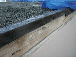
[4]When completing wind design for roofing, most designers start with NBC. Part 4, “Structural Design,” outlines the formula used to determine the pressures applied to each building surface. This is further explained in the NBC Structural Commentary Guide, which provides the pressure applied to the structure without safety factors (i.e. 2.4 kPa [50 psf]). Where does one go from here and what does it mean?
Many designers would then insert a line in the specification stating the roof assembly should meet the requirements of FM 1-60. The problem is FM 1-XX rating wind uplift requirements do not have built-in safety factors. Instead, the calculation completed through the FM Global standards provides the safety factor, so the numbers completed from NBC cannot be used to compare to the wind uplift requirements. Even the FM Global calculation has different variables and factors than the calculation contained within NBC. Currently, there are no standards for designers to refer to in NBC, wherein they may apply the information from the calculations completed through Part 4 of the building code and select a roof system.
 [5]
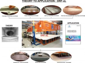
[5]However, this is all about to change. Over the past decade and a half, a group called the Special Interest Group for the Dynamic Evaluation of Roof Systems (SIGDERS) (Visit sigders.ca[6]). has been working toward the goal of having a unified standard and calculation tool for use with NBC. The new Canadian Standard Association (CSA) A123.21-10, Standard Test Method for the Dynamic Wind Uplift Resistance of Membrane-roofing Systems, has been developed to assist designers in designing and selecting the right assembly to withstand wind forces. The interesting part of this standard is it breaks away from the normal thinking of testing.
Available design standards
Both the FM Global and Underwriters Laboratory (UL) standards are for static wind uplift design; this means the roof is pressurized to a specific pressure and held for one minute. Once the minute is up, if the membrane has not failed, it is deemed to have passed that pressure category. Of course, no wind storm has a nice, constant wind speed that never changes direction. The CSA standards actually take into account the frequency of gusts and varying intensity, and more accurately replicates the actual wind effects to which the building will be exposed. It also allows use of the calculation from NBC Part 4 to accurately calculate wind speed.
Roof assemblies conforming to CSA A123.21 must be tested to determine the roof assembly’s wind uplift performance. Currently, Exp Global is the only certified testing laboratory; it tests roof assemblies from manufacturers and provides reports on its website outlining:
- wind pressures to which the roof is tested;
- design wind pressures (with safety factor); and
- acceptable components within the assembly, including insulation and vapour barrier types and thicknesses. (For more information, visit www.exp.com/en/rooftesting[7]).
CSA A123.21 is rumoured to be implemented in the current code cycle which should be out this year or the following one in 2015. This would include mechanically attached roof membrane systems, as well as adhesively attached roof systems. This will finally provide a single source guide for the design and selection of roof assemblies that also is derived from NBC requirements.
 [8]
[8]Images courtesy NRC
Perimeter edge flashings
The designer knows how many fasteners to use, and that the corners and perimeters need more than the rest of the roof. He or she has a well-designed roof assembly, but should remember the majority of catastrophic roof failures start at the perimeter flashings. There currently is no standard for perimeter flashings that can be used to design based on the existing NBC, not to mention there is no calculation within the code for determining the wind forces exerted on the flashings.
Within the industry, many of the roof flashings installed have an inseam clip every 3 m (10 ft) and, at best, mechanical fasteners on the interior surface of the flashing. However, the majority of the wind pressure is applied to the exterior face of the metal and results in it prying off. Typically, exposed fasteners are not installed on the exterior face from an appearance or architectural viewpoint. As this face is usually visible, a cleat or clip installed in the drip edge is appropriate, but rarely done.
A properly designed cap flashing will almost always have a continuous cleat or clip installed in the drip edge of the external face of the metal or exposed fasteners. When a cleat or clip is installed in the drip of a flashing, it is usually 100 to 150 mm (4 to 6 in.). At this length, the cleat does not have enough strength to adequately resist wind forces.
Another area where cleat design or installation is overlooked is the gauge of the metal. Typically, the cleat needs to be one gauge heavier than the cap flashing, but this will vary depending on the forces, the type of metal used, and the configuration of the drip edge/hem. When exposed fasteners are used, the frequency of the fasteners is quite high, typically 450 mm (18 in.) on centre (oc) or higher, again, depending on the variables. However, adequate frequency of exposed fasteners is rarely achieved.
 [9]
[9]Flashing standards
There are very few standards or guidelines designers can use to assist with the design of perimeter cap flashings. The standard most people refer to is American National Standards Institute (ANSI)/Single-ply Roofing Institute (SPRI) standard ES-1, Wind Design Standard for Edge Systems Used with Low-slope Roofing Systems. (For more, visit www.spri.org[10]). This provides guidelines on how to calculate pressures on various types of flashings and that the flashing must be tested to meet the design. As with the UL and FM Global standards, it is a static test and does not closely represent the true affect of wind on a building.
ANSI/SPRI ES-1 is not directly referenced by NBC. Nevertheless, Appendix A, “Explanatory Material,” A5.6.2.1, “Sealing and Drainage,” references two guides for flashing design to prevent moisture entry. These guides––Sheet Metal and Air-Conditioning Contractors National Association’s (SMACNA’s) Architectural Sheet Metal Manual and the National Roofing Contractors Association’s (NRCA’s) Roofing and Waterproofing Manual––both use ANSI/SPRI ES-1 for their flashing design details. However, there is always a catch; in this case, the calculation on which the standard is based does not include Canadian weather data. As noted, one cannot take NBC data and use it to perform the calculations either.
Currently, the National Research Council of Canada (NRC) (Visit nrc-cnrc.gc.ca[11]). is working with industry stakeholders and the University of Ottawa to develop a calculation tool and testing protocol for perimeter flashings. Still in its infancy, the project is the first attempt to accurately simulate the dynamic effects of wind on perimeter flashings, and will be based on NBC’s terminology and requirements. This standard will be another part of CSA A123.21; however, it will not be completed for several years. In the meantime, designers will have to use the resources available and rely on local knowledge or compare to similar areas within the country’s neighbours to the south to assist in perimeter flashing design.
Conclusion
Whenever a roof is going to be installed on a building, a designer must complete a wind uplift design for it. This must include perimeter flashings and accessories for the long-term success of the roof to be realized. Although there may be a lack of available resources, one must use the information available to ensure well-performing roofs are achieved.
Josh Jensen, AScT, CHI, RRO, RRC, is an associate and manager of the roofing division of JRS Engineering, a building envelope and roofing firm providing service in Western Canada and the northwestern United States. With almost a decade of roof consulting design and investigating experience, he received his education from the British Columbia Institute of Technology (BCIT). Jensen is actively involved in industry development, and currently serves on the standards technical panels for Underwriters’ Laboratories (UL) roof wind uplift resistance and roofing covering testing standards, and the National Research Council of Canada (NRC) panel for roof edge system technology. He can be reached via e-mail at josh@jrsengineering.com.
- [Image]: https://www.constructioncanada.net/wp-content/uploads/2015/12/11.jpg
- [Image]: https://www.constructioncanada.net/wp-content/uploads/2015/12/21.jpg
- [Image]: https://www.constructioncanada.net/wp-content/uploads/2015/12/31.jpg
- [Image]: https://www.constructioncanada.net/wp-content/uploads/2015/12/4.jpg
- [Image]: https://www.constructioncanada.net/wp-content/uploads/2015/12/51.jpg
- sigders.ca: http://sigders.ca
- www.exp.com/en/rooftesting: http://www.exp.com/en/rooftesting
- [Image]: https://www.constructioncanada.net/wp-content/uploads/2015/12/THEORY-TO-APPLICATION.jpg
- [Image]: https://www.constructioncanada.net/wp-content/uploads/2015/12/Joshpaper.jpg
- www.spri.org: http://www.spri.org
- nrc-cnrc.gc.ca: http://nrc-cnrc.gc.ca
Source URL: https://www.constructioncanada.net/wind-design-for-roofing-misconceptions-and-consequenes/