Insulating glass: Compensating for internal pressure changes
by brittney_cutler_2 | July 11, 2022 4:00 pm
 [1]By Amy Roberts
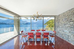
Today’s windows and glazed areas almost universally employ insulating glass units (IGUs) to improve thermal performance with double or triple panes of glass. The panes usually are annealed, heat strengthened, tempered, or laminated, and tinted or with low-E coatings. The space between the panes is filled with desiccated air or with an inert gas.
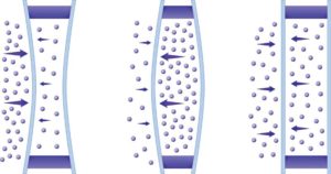
These are not rigid assemblies. The glass panes on either side of the central cavity can bow in or out as ambient air pressure increases or decreases compared to the pressure of the internal gas. The change can be temporary as elevation varies during shipment or as weather (temperature and barometric pressure) fluctuates after installation. It also can be permanent due to the elevation of the installation site versus the manufacturing location. Over time, the resulting glass deflection can cause failure of edge seals and spacers and, in extreme cases, glass breakage.
This can be prevented through careful design specifications which anticipate jobsite conditions, and by using special devices to equalize internal and external pressure. The following guidelines and additional information are available in the newly published Fenestration and Glazing Industry Alliance (FGIA) manual, IGMA TM-3200-21, Design Considerations for IGU Cavity Pressure Compensation.[2]
Site-specific design
Basic physical laws govern the interrelationship among gas pressure, volume, and temperature. The ideal gas law equation to calculate the change in gas pressure between two sets of conditions, based on deflection of glass lites, is expressed as:
P1V1/T1 = P2V2/T2
where:
T is absolute temperature.
V is absolute volume.
1 is the location where the IGU was manufactured.
2 is the travel conditions and final construction location where the IGU is installed.
 [3]
[3]In general, as the IGU temperature increases, the volume of gas inside the IGU tends to increase relative to its original volume, causing increased interior pressure and outward deflection of the glass panes. This also occurs if the elevation is higher with attendant lower air pressure at the construction site than at the manufacturing site, or when the barometric pressure at the final location where the IGU is installed drops below average during weather events.
Conversely, if the temperature decreases or, if the elevation is lower than the manufacturing location, the volume of gas inside the IGU decreases. This causes inward deflection of the glass panes. IGUs experiencing such pressure-induced deflection can fail from glass breakage or pressure overloading of the edge seal. Those with operable sash may experience frame deflection which will compromise proper operation.
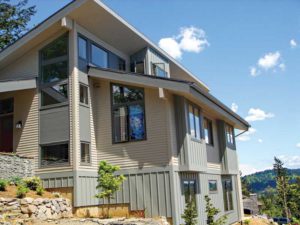
In addition, during the IGU’s transportation from its fabrication site to its final installation site, it may undergo multiple elevation changes. For instance, a shipment from a midwestern U.S. state to the Canadian West Coast will travel through the Rocky Mountains. Along the journey, it will experience multiple elevations and, concurrently, short-term relative pressure changes between the IGU and ambient air. Such elevation change creates a pressure differential between the IGU glazing space and the exterior environment which, unless alleviated, can cause the noted failures.
 [4]
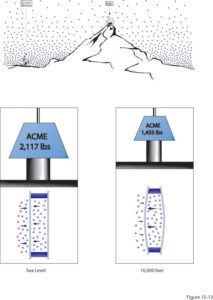
[4]While these in-transit pressure intervals may be short, lasting several minutes to several hours, they may be quite extreme when elevation differences approach 3048 m (10,000 ft). For example, if an IGU is manufactured at an elevation of 1219 m (4000 ft) and adjusted at the factory for sea-level pressure, but it goes over a 3048 m (10,000 ft) pass on the way to its final installation site, it will experience the full 3048 m (10,000 ft) difference compared to sea level. Whether or not the edge seal breaks depend on the exact makeup of the IGU.
Referring to the equation for gas pressure change, if the starting elevation at the manufacturing site is known (P1), and the elevation at the final installation site is known (P2), and the volume of air or gas in the IGU is known (V1), then a professional (such as an engineer) who may or may not be employed by the IGU manufacturer, can calculate V2 for the volume of air or gas at the destination and submit the results to the specification professional.
In addition to the ambient conditions, the amount of glass deflection is also dependent upon the interplay of many configuration-related variables. These include glass type and thickness, glass area, dimensional geometry (aspect ratio), framing profile design and material, IGU cavity width, edge seal design and materials, sealant and spacer selection, and spacer size.
Pressure compensation
 [5]
[5]Generally, IGUs are specified and designed to withstand breakage or other effects from these dynamic and static forces. In some cases, the fenestration manufacturer or IGU fabricator will provide units that will be permanently deflected at the installation location but are well within the tolerance of breakage.
In other cases, some IGUs are manufactured or installed with a pressure compensation scheme that adjusts internal gas pressure based on the intended final installation location. It is up to the IGU fabricator to determine how to achieve this. Each approach has advantages and disadvantages, as well as need certain considerations during installation (glazing).
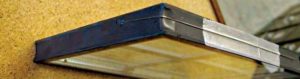
Capillary or breather tubes
In this method, permanent air tubes are inserted in air-filled IGUs after fabrication to allow for pressure equalization. Stainless steel capillary tubes have an inside diameter of 0.53 mm (0.021 in.), while aluminum tubes have a diameter of 0.81 mm (0.032 in.). In this method, permanent air tubes are inserted in air-filled IGUs after fabrication to allow for pressure equalization. Stainless steel capillary tubes have an inside diameter of 0.53 mm (0.021 in.), while aluminum tubes have a diameter of 0.81 mm (0.032 in.). Although similar, breather tubes, made of metal or plastic, are significantly larger with a diameter of 3 mm (0.12 in.) but are not as common as capillary tubes. Note, neither capillary or breather tubes are applicable for argon or krypton gas-filled IGUs.
 [6]
[6]Installing contractors and glaziers should follow the fabricator’s instructions on where the tube is to be placed in relation to the top, sides, or bottom of the installed IGU. Usually, the tube is positioned near the top of the IGU pointing down and is sealed prior to the glazing operation. Specify that the tube must have adequate clearance from the glazing frame or accessories within the glazing system during installation.
For IGUs which are pre-glazed and shipped to the construction site prior to sealing, the framing system should be specified to provide access to the capillary tube so proper sealing of the tube can be carried out onsite within the timeframe designated by the fabricator.
Daily fluctuations in cavities pressure-compensated with open capillary tubes are covered in FGIA’s document, IGMA/GANA TB-1601-95(14), Guidelines for Capillary Tubes.
Desiccant adsorption/desorption
 [7]
[7]In this approach, a sacrificial gas typically is adsorbed from the cavity into a desiccant material. This reduces the pressure in the cavity relative to the atmospheric pressure at the time of manufacture. It also allows sealing at atmospheric pressure, without the need to puncture the spacer or glass for pressure adjustment after sealing.
The sacrificial gas must be mixed into the insulating gas at the time of filling. The desiccant must adsorb the sacrificial gas, but not the insulating gas. The IGU likely will be glazed with its glass bowed slightly inward. This bow will need to be accounted for when adding accessories like tape-applied grills to the glass.
While there are other methods, it stands to reason the geographical location of where the IGUs are manufactured and where they typically ship would affect the need for compensation methods. For example, if a manufacturer is in Vancouver, British Columbia, and all of the IGUs are shipped to Calgary, Alberta, they would need to have a compensation system in place.
Pre-inflating/pre-deflating
 [8]
[8]IGUs initially can be made with a preset positive or negative pressure, induced by pre-inflating or pre-deflating during fabrication. This is achieved by removing or injecting gas to increase or decrease the volume by a specific amount, which mimics the effect of the atmospheric pressure typical of the installation site. This allows the glass to be manufactured at one elevation and adjusted to the desired cavity condition at its pre-determined destination. Pre-inflating/deflating is a method used to adjust a unit for its elevation at the final destination. In many cases, however, it does not compensate for changes in elevation during transit to the final location. Depending on the application, pre-inflating/deflating may help lower the effect of elevation changes during transit or it may make them worse.
Pre-inflated or pre-deflated IGUs will likely have a convex or concave shape during glazing if they are installed at an elevation that is the same as where they were manufactured. The degree of concavity/convexity can vary significantly depending on the size, aspect ratio, and degree of pre-inflation/pre-deflation.
This method does have some limitations and may not work for all IGU configurations due to increased stress on the glass. Pre-inflated/pre-deflated windows may be unable to operate until they reach the design elevation. This is especially true of horizontal and vertical sliding windows that are convex after adjustment. Pre-inflated/pre-deflated IGUs also can cause challenges related to installation of external muntin bars.
Adjustment of IGUs for change in elevation may induce additional stress on the edge seal from the time of manufacture until it reaches its final installed elevation. Many IGUs can handle this added stress, but the degree of stress, the size of the IGU, the spacer, the sealant, and the glass all need to be considered to determine when pre-inflation/pre-deflation is appropriate.
Temperature manipulation
Here, the environment is controlled through heating or cooling of the entire IGU prior to sealing and/or gas filling, affecting the volume according to the gas pressure equation. Temperature manipulation also will cause convex or concave conditions in the IGU at the time of installation.
Bladder relief system
Specifying the use of a flexible container, also known as a ‘bladder’ system, can counter pressure differentials due to elevation changes between the points of manufacture and installation. These pressure changes can be intensified by internal heating of the IGU due to the radiant effects of the sun, which are common at higher elevations. A bladder system acts as a mechanism for relieving this accumulated pressure differential over a brief period. It can be temporary, such as for use during transport, or permanent upon installation at the final construction site.
A bladder is attached to the IGU cavity, typically via an access tube, to control the internal pressure during shipping. Commonly made of coated plastic or foil, the bladder is removed once the IGU has reached the jobsite and then is sealed. Be aware bladder access tubes may not be of sufficient diameter to enable pressure equalization over such short periods of extreme pressure changes experienced during transit. Such IGUs should be treated as if there were no access tubes and packaged to effectively manage glass and edge seal stress.
Permanent bladder application is like what is used for transportation, but the bladder stays active to occasionally equalize pressure as needed throughout the life of the IGU. It can be used for a single IGU or in parallel with multiple IGUs.
When installing IGUs using a flexible container/bladder system, the installing contractor or glazier should take care to confirm:
- The IGU is glazed in accordance with the bladder manufacturer’s written recommendations.
- The IGU is fabricated with a bladder system that will remain permanently operational for the life of the IGU, and all tubing connections do not leak.
- For IGUs fabricated with bladder systems, where the bladder will be removed and access tubes sealed at installation, the IGU and/or bladder manufacturer’s written instructions for removal must be provided. Proper removal of the bladder should ensure no damage occurs to the IGU’s edge seal, and the access tube itself is properly sealed.
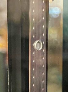
Post fabrication valving
In this approach, a secondary fabrication process is needed at, or near, the installed location. It typically involves using a one-way valve installed into either the IGU spacer or one of the glass panes before gas filling occurs. Such valves are specified and designed to be mechanically depressed under a specific differential pressure load to adjust the pressure in the cavity relative to the atmospheric pressure at the manufacturing site. After venting, the valve returns to a closed position, usually under a spring load. This method requires the valve to remain uncovered during transport for pressure adjustment after installation of the IGU.
When the IGU is glazed, the valve can be actuated to allow proper pressure equalization venting. Placement of setting blocks and glazing sealant should be evaluated when locating the valve to avoid restricting airflow of the valve outlet. Additionally, mechanical loading of the valve by framing material could cause stress in the sealing and mounting of the valve should be verified to prevent moisture or gas leakage.
The IGU must be specified and designed to have sufficient strength to perform under cyclical thermal loads, seasonal temperature changes, and at the venting pressure of the valve. Calculations will ensure the proper valve is used so the IGU’s final internal pressure at the time of installation will be within the design limits of the edge seal.
Conclusion
Each of these pressure equalization methods and their associated application guidelines is covered in thorough detail in IGMA TM-3200-21. For each approach, this manual addresses advantages and disadvantages, and provides factory-to-field recommendations for manufacturing and quality, storage and shipping/handling, installation (glazing), and considerations for dealing with environmental conditions to which the IGU will be exposed at all stages. Commercially available software programs which can address the germane variables and predict the glass deflection also are listed in the manual.
Author
 [9]Amy Roberts is Fenestration and Glazing Industry Alliance’s (FGIA’s) director of Canadian and technical glass operations. She oversees FGIA’s Canadian standards and regulatory building and energy codes, as well as the Insulating Glass Manufacturers Association of Canada (IGMAC) certification program for insulating glass units (IGUs). Roberts has more than 20 years of industry experience in glass and insulating glass (IG) manufacturing, and in both residential and commercial window manufacturing.
- [Image]: https://www.constructioncanada.net/wp-content/uploads/2022/06/4MountainHome.jpg
- Fenestration and Glazing Industry Alliance (FGIA) manual, IGMA TM-3200-21, Design Considerations for IGU Cavity Pressure Compensation.: http://FGIAonline.com/store
- [Image]: https://www.constructioncanada.net/wp-content/uploads/2022/06/2UnitBeingFilled-Tube_Shutterstock.jpg
- [Image]: https://www.constructioncanada.net/wp-content/uploads/2022/06/1Tube_RandiErnst.jpg
- [Image]: https://www.constructioncanada.net/wp-content/uploads/2022/06/3ArgonPlug_JeffHaberer.jpg
- [Image]: https://www.constructioncanada.net/wp-content/uploads/2022/06/5MountainHome_SeriousGlass.jpg
- [Image]: https://www.constructioncanada.net/wp-content/uploads/2022/06/Graphic1_RandiErnst.jpg
- [Image]: https://www.constructioncanada.net/wp-content/uploads/2022/06/Graphic2_RandiErnst.jpg
- [Image]: https://www.constructioncanada.net/wp-content/uploads/2022/06/Roberts_Headshot.jpg
Source URL: https://www.constructioncanada.net/insulating-glass-compensating-for-internal-pressure-changes/